Half Bridge Motor Controller Basics

Thread Starter

john_nohj

Joined Dec 10, 2014
6
I have a pretty basic question about half bridge motor controller design...

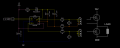
I am working on a half bridge controller that I want to drive fairly high currents, so will require the use of multiple high side and low side power FETs.
My design is so far based on the NCP5183 High side bootstrap and Low side driver IC.

My circuit design uses 3 of these ICs each driving a single high and low side power FET pair, with the power FETS driving the the motor in parallel.
If I run the circuit so that only a single NCP5183 and power FET pair is driving the motor driver then the system works perfectly.
However when I try and get these 3 circuits driving together the high side power FETs stop switching correctly. The waveform of the high side power FETs becomes very erratic.

After spending a lot of time researching this I have come to the conclusion that the normal way to design a half bridge is to have a single driver circuit, and to drive multiple power FETS gates at once (with the gates connected together). However as described my circuit has multiple driver circuits driving single pairs of FETS.

So my question is, firstly am I correct in thinking that my design is flawed, and secondly what causes the system to stop operating properly when designed like I have?
 

danadak

Joined Mar 10, 2018
4,057
Yes a single driver, because of timing differences chip to chip, is preferred.

But compromise is now, for parallel-ed fets, you have a ton of gate capacitance
to drive. And all that gate drive charge has to flow thru driver, that in turn is
a challenge to get right, layout, wiring, stray C, thermals.....Do the thermal
calculations, online lots of app notes on this topic.

https://www.google.com/url?sa=t&rct=j&q=&esrc=s&source=web&cd=1&ved=0ahUKEwiWneOn2_jaAhXHi1QKHf-oBzsQFggpMAA&url=https://www.infineon.com/dgdl/para.pdf?fileId=5546d462533600a401535744b4583f79&usg=AOvVaw0QlUf5rYqHFpw0XJhiIbf2

"Stopped working", does PWM have sufficient dead band settings, as shown in
attached timing diagram.


Regards, Dana.
 

Attachments

Last edited:

Thread Starter

john_nohj

Joined Dec 10, 2014
6
Hello danadak, thankyou for your quick reply!

To answer your question the dead band is set to 300us. In fact I tested that the problem wasn't being caused by shoot-through by increasing the dead-band substantially. I am using a PIC micro-controller in half-bridge mode to produce the PWM signal, so this is easily adjustable.


Thank you for the document, I will have a good read though.
I also think that I am just going to redesign the driver circuit to use a single driver.

I am using IPT020N10N3 FETs, which have pretty big gate capacitance anyway.
Much more reading to do....
 

-live wire-

Joined Dec 22, 2017
959
Measure the current through the motor and the current it all draws. If it draws a lot more current than is going through the motor, then the timing differences may be causing momentary shorts. You may need to use drivers with more synchronized timing to avoid this.
 

ebp

Joined Feb 8, 2018
2,332
A schematic would be helpful, as would an explanation of how you are using the half-bridge. A half-bridge is usually used with another half to make a full bridge or used to implement run-coast-brake operation. What voltage and current are involved?

Depending on what is being done, a charge pump for the high side driver may be unsuitable.

300 µs of non-overlap is normally extraordinarily long, but quite acceptable for typical motor drive half-bridge.

I see nothing fundamentally wrong with using three drivers as described. There may, however, be timing issues or layout issues that lead to misoperation. The datasheet for the driver suffers from having been written in pseudo-English.
 

danadak

Joined Mar 10, 2018
4,057
You mentioned deadband is 300 uS, is that a typo ? What is your PWM frequency ?

In general this is a challenging design because of current levels, power, gate capacitance.

What is the load being driven ?

There are lots of ap notes on web for calculating Pdiss in gate drive, yopu
will need that for sure.

Regards, Dana.
 

Thread Starter

john_nohj

Joined Dec 10, 2014
6
Sorry, yes that was a typo. It should have been 300nS.
The PWM freq is ~16kHz.
I read the datasheet for the NCP5183 thoroughly and performed the calculations as per the datasheet.

I am planning to use the half bridge to control a large brushless DC motor at variable speeds, in one direction only.
I have been testing the system at 12Vdc, with a small 5A motor load, just to prove the control electronics at this point, but intend to move up to several kW 24Vdc motors at some stage.

I have attached a screen shot of the driver circuit. I have 3 of these driver circuits on the PCB. As stated previously, with just one driver circuit operating the system works fine. However when all 3 work in unison the PWM signal at the high-side FET gates becomes very errratic.

With all 3 drivers operating - at the lowest PWM setting (Highside = 10% duty) the HS gate waveform is ok. If the duty is turned any higher than the signal at each highside FET gate seems to turn off randomly during the on time, and sometimes not come on at all. Unfortunately I cant send a picture of the scope because the camera doesn't really capture what is happening properly. The problem was alleviated slightly by reducing the size of the bootstrap caps to 300nF, allowing a slightly longer HS duty cycle, but not much.
I have a suspicion that this could be due to the UVLO feature of the chip but not entirely sure. I have spent a long time trying to work this out, but a bit stumped at this point.
However a this point I feel i may save myself more time in the long run by re-designing the circuit for a single driver.

Just to make it a bit clearer on the schematic the control PCB sits on top of the FET PCB, and the FETs are directly underneath the connectors on a second PCB. I drew in the FET connections with shapes just to make this a bit clearer.
 

Attachments

ebp

Joined Feb 8, 2018
2,332
I think it very likely that UVLO is turning off the high side FET because the bootstrapped supply voltage falls too low. The disable threshold (falling voltage) is 7.2 to 9.1 V. Given that your driver supply is only 9 volts and you have a diode drop to contend with, you are within the turn-off range under the best of circumstances unless HB is pulled negative with respect to ground - which is normally something that must be carefully avoided, or at least severely limited in magnitude. Normal operation of the charge pump relies on HB being pulled very close to ground by the low-side driver frequently enough to replenish the charge lost to driving the gate of the high-side driver. Since the low-side driver is presumably not being turned on at all during normal running of the motor, there seems little chance of this happening. In the typical application of a charge pumped high side driver, the expectation is that the high and low sides will each be turned on every complete switching cycle.

As I mentioned previously, this is a case where a charged pumped high side gate supply is probably just not workable. Even if you reconfigure so that the low side driver is used for "run" and the high side for braking, you may lose control during braking. An isolated DC-DC converter module (quite inexpensive and compact for the power required) may be the best choice for the high side gate supply. An alternative is to use a transformer to drive the high side FET.
 

Thread Starter

john_nohj

Joined Dec 10, 2014
6
Hi EPB thank you for your reply. I really feel like I'm getting somewhere now!

OK, so the lowside FET is being switched as well, and actually I am aware that the LS FET needs to be switched to allow recharging of the bootstrap cap. At full motor speed the duty cycle of the HS Fet is no more than ~95%, to allow this to happen. I know I cannot just have the HS FET fully on with my design.

I had previously tried fitting 330uF caps across the driver IC supply which helped alleviate the problem very slightly. I have also probed the HB line and it is not dropping below 0 significantly.
I am convinced it is a UVLO problem now, after reading your reply. When I look at the scope this makes sense as well.

I am going to increase the driver voltage to 10V and see how I get on.

Thank you all very much for your help.
 
Top