H-Bridge Driver Problems

Thread Starter

sgardner025

Joined Nov 5, 2009
79
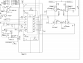
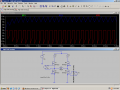
OK, I'm pulsing the low side ,so I thought that low side sensing was the way to go. But... Here is a sim with resistors on the high side. The current through R1 is showing the same as L1. I like the idea of high side sensing because of the added short circuit protection.
 

Attachments

SgtWookie

Joined Jul 17, 2007
22,230
Remember, commonly available comparators (like LM311, LM393, LM339) can sense to ground, but cannot get within more than about Vcc-1.5v.

High-side sensing is sometimes the way to go, but it does somewhat complicate things.

If you really want to get away from the Rsense power losses and difficulty of high-side sensing, you might consider looking into using Hall-effect sensors.
 

SgtWookie

Joined Jul 17, 2007
22,230
You might use the resistance of a trace on the board as a resistor. You really can't use a "normal" SMT/SMD resistor for that much current, as it would vaporize.

There are calculators for copper weight vs trace width vs thermal rise vs resistance.

For example, 200mil wide trace, 2 Oz copper on board, 19A current, 3.62" long trace, 4.99mOhms, 94.8mV drop.

PCBtemp is a useful trace calculator available for a free download. Google's your buddy here.
http://www.smps.us has various calculators available.
 

Thread Starter

sgardner025

Joined Nov 5, 2009
79
It's been a long while since I have had time to look at this. The circuit is better off now than before, no components are getting killed anymore. The problem now is that the high side mosfets aren't being turned on fully. The voltage from gate to source on these is only hitting about 7.5 volts. Vcc/Vdd is dropping down to about 8.2 volts when the lower fets start switching. C1 and C2 are .68uF at the moment, not .1 like the diagram shows. Any ideas on why the voltage is drooping so much? I have attached an updated drawing and the data sheet for the voltage regulator I am using.
 

Attachments

Thread Starter

sgardner025

Joined Nov 5, 2009
79
I believe it's fixed now, it looks like there was a bad solder connection on the board. The Vcc/Vdd voltage is holding now. Gate-source voltage for the upper mosfets is reading ~12 volts.
 

SgtWookie

Joined Jul 17, 2007
22,230
Glad you figured it out.

Sorry I didn't get back to you earlier; many things going on both here on the board and here in my house.
 

Thread Starter

sgardner025

Joined Nov 5, 2009
79
Yeah it's pretty busy here too. Thanks everyone for all the help. So far it's running good in my test tank. Now I need to get this thing on the water for some real world testing.
 
Top