H-Bridge Driver Problems

Thread Starter

sgardner025

Joined Nov 5, 2009
79
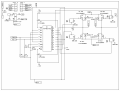
It's been a while since I have posted here, been busy with work and kids playing ball. I posted a while back about using the HIP4081A full bridge driver and I've finally started on it, but there's trouble. I started out driving the motor forward and everything seemed fine, except for I was only reading 8.5 volts across the motor at full speed. Then I went to reverse and it worked for a few seconds then something happened. Forward still worked but no reverse. It acted like it wanted to start in reverse and then nothing. Well I went back to see if forward was still working and it did for a few seconds then Q2 starts smoking, and now the HIP4081A is dead and Q4 is shorted all the way around. Q2 still reads open but I'm not sure about its operation. I didn't have a fuse on the control circuit but did have a 40 amp automotive circuit breaker in line with the + terminal of the battery but it never tripped. I don't know exactly how much current the motor is supposed to draw, it's a trolling motor. Anyway, I've posted a schematic of the bridge circuit and some data sheets. Could someone look over the schematic and let me know if you see any problems? I was using a 250Hz signal from a op-amp on the inputs at about 9 volts. Also, could someone shed some light on the bootstrap capacitor calculation. I used equation 4 example from the HIP app. notes (with my values) and came up with .124uF. I don't have any dead time added to the input circuit, that's the only thing I can think would be causing problems. I'm not sure what to look for as to what killed the HIP4081A though. Thanks in advance guys for the help.
 

Attachments

SgtWookie

Joined Jul 17, 2007
22,230
I see you're using 0.15uF caps for the bootstraps (C1,C2). The application note suggests a value of 0.22uF to 0.5uF. It looks like those MOSFETs have a total gate charge of around 115nC, which is quite a bit.

I would increase your bootstrap caps to around 0.47uF, using low-ESR caps.
I would reduce the resistance on the gates down to around 4.7 Ohms. The resistors should be as close as possible to the MOSFETs themselves. Having those large gate resistors is slowing down your switching times a good bit. I'd get rid of the diodes around the gate resistors.
Replace R45 with a piece of wire.
Replace R46 with a piece of wire.
You don't want resistance in your bootstrap caps' charge or discharge path.
 

rjenkins

Joined Nov 6, 2005
1,013
You need dead time, otherwise the transistors will briefly short the supply at each changeover.

I'm not sure what motor you are using, but if you have a 40A breaker I'm guessing it's quite large. The other critical thing on serious sized motor controllers is current monitoring and feedback.

If you try and change the motor speed suddenly, the current will be enormous. You must monitor this and limit the rate of change of the PWM ratio to prevent excess current. This applies equally to slowing down as well as speeding up.

You should also have an absolute limit current, just above the 'working' current limit, that turns the bridge off completely when exceeded and locks out until power is removed.

Note that to protect semiconductors, you need either electronic protection (as above) or 'ultra rapid' semiconductor rated fuses (aR, uR types etc). Normal fuses or circuit breakers will only blow after the transistors have shorted out.
 

rjenkins

Joined Nov 6, 2005
1,013
I've just had another look at the 4081 data.

It has the facility for internally controlling the dead time, see info on HDEL and LDEL (pins 8 & 9 on the DIP package).
As you are using a very low switching frequency, you can go to near the maximum delay - try using 220K resistors on those pins (to VSS).

The switching frequency itself could be a problem.
The idea of PWM (or Class D amps) is that the switching or carrier frequency is way above the possible responce of the load, so only the modulating signal has an effect on the load current.

At only 250Hz, you will probably be getting AC through the motor. You need to increase the carrier frequency so there is no significant carrier current through the motor, and/or add a series inductor to reduce the carrier effect.

In the 4081 datasheet, the lowest carrier shown is 10KHz & up to 1MHz.
This also means the bootstrap caps will be supplying power for 40 times longer at 250Hz than they would at 10KHz & the datasheet values may be based on that minimum, so the gate drives may be failing.
 

Thread Starter

sgardner025

Joined Nov 5, 2009
79
Thanks for the replies guys. I installed D3-D6 because the app. note mentioned using them to aid in mosfet turn off. Could someone point me to some information on current monitoring and control? Thanks again for all the help.
 

Thread Starter

sgardner025

Joined Nov 5, 2009
79
Could I use low side current sensing to limit the control input signal by pulling it down with a transistor, after a certain amount of current starts to flow? Also, with low side sensing, is it better to look at the signal the way it is or to use a filtered version?
 

SgtWookie

Joined Jul 17, 2007
22,230
I haven't looked at this for several days, so I forget where you're applying PWM.

If you're PWMing on the high side, you'll need to monitor current on the high side.

If you're PWMing on the low side, you'll need to monitor current on the low side.
 

Thread Starter

sgardner025

Joined Nov 5, 2009
79
I think I will try using the DIS pin of the driver in conjunction with current monitoring, or does this sound like a bad idea?
 

SgtWookie

Joined Jul 17, 2007
22,230
I'm really a bit too tired at the moment to re-analyze your circuit.

However, keep in mind that when you turn off the current to the motor, it doesn't stop instantly; instead the current is recirculated through the motor via the diodes and MOSFET body diodes.

If you don't account for this recirculated current, you'll be reading roughly 1/2 the actual motor current.

Try creating a simple simulation using a SPICE emulator, and you will see what I am talking about.
 

rjenkins

Joined Nov 6, 2005
1,013
The current monitoring needs to be (initially) unfiltered.

You could use low side monitoring, on both legs of the bridge, either VERY low value resistors (so you don't significantly affect the gate-source drive voltage), current sense FETs (which have a tap connection from the source which gives a percentage of the total current), or hall effect sensors.

The safety part should work on the unfiltered sense signal and do an instant, latched turnoff if the current reaches the bridge safe values.

The current loop feedback signal should be filtered to remove the PWM carrier and give a stable current reading.

At the simplest level, this signal could momentarily disable the bridge outputs to slow the acceleration and keep the motor current to a reasonable level.
 

Thread Starter

sgardner025

Joined Nov 5, 2009
79
The safety part should work on the unfiltered sense signal and do an instant, latched turnoff if the current reaches the bridge safe values.
I'm not sure what value to use here. I have some new information and the motor should draw ~30 amps full load. I understand the limiting part.

As for the sense resistor, is it not feasible to use just one, with the sources of the bottom two FET's tied together and going to the resistor, then to battery -?
 

SgtWookie

Joined Jul 17, 2007
22,230
You need to experiment with a simple H-bridge model to see what's going on with the current flow.

If you don't have LTSpice, download it. Google is your friend.

Attached is a minimalistic H-bridge; upper side being PWM'd on the left, lower side held on.
Notice that the current through R1 (sense resistor) is roughly half of the current flowing through the inductor. That's because of the current recirculating through the MOSFET body diodes.

Running the simulation and viewing current flow in various areas will help you to better understand what will happen with a real H-bridge.

After you understand the current flow with the single sense resistor, try making two individual current sense resistors to ground.
 

Attachments

Last edited:

Thread Starter

sgardner025

Joined Nov 5, 2009
79
I see what you mean about the current. The inductor/motor current is held at a higher level continuously. I noticed the peak values being the same, but then the resistor current is cut off. So should I just look for about half the current? If I wanted to start limiting at say 38 amps, could I just look for ~19 amps at the resistor?
 

SgtWookie

Joined Jul 17, 2007
22,230
No.

Notice that as soon as the MOSFET turns off, current through Rsense drops to 0.

Your circuit will think - Oh, OK - let's turn on the juice!

And as soon as the MOSFET turns back on, your circuit will see that it's already over the limit, and turn it off. And do it again, very rapidly.

Your MOSFET will be turned on and off as fast as your circuit will drive the gate. Your MOSFET will be dissipating a lot of power due to the increased amount of time that it is operating in the linear region, and burn up.

As much as you'd like to, you can't get by with just a single sense resistor on the low side.

Did you try putting in another sense resistor?

Did you notice how having individual sense resistors causes the current to be properly measured?

If not, try the attached simulation.
 

Attachments

Top