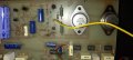
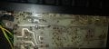
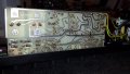
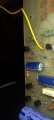
Take well focused photos of both sides of the board so that we can reverse engineer the circuit.
Take the photos as one board and also as two sections (six photos in total) so that we can get good close ups. We want to be able to read the colours on the resistor.
Also, write down the part numbers of the black transistors and their locations.
Have those two output transistors been checked yet" At this point it could be either an open transistor or a shorted transistor.
Do we know if the amplifier is direct coupled or is it capacitor coupled?
Have those two output transistors been checked yet" At this point it could be either an open transistor or a shorted transistor.
Do we know if the amplifier is direct coupled or is it capacitor coupled?
Have those two output transistors been checked yet" At this point it could be either an open transistor or a shorted transistor.
Do we know if the amplifier is direct coupled or is it capacitor coupled?
According to some folks, using a bipolar power supply for the output reduces the distortion from the coupling capacitor. That is not my assertion, it comes from other folks.
My reason is that a split supply is just a better choice. The detailed explanation is rather tedious.
And the big benefit of a direct coupled amplifier is that it makes servicing more difficult and it allows any transistor problem to take out the power transistors and burn out the speaker.
This is designed and sold as a bass guitar amplifier. The output to the loudspeaker is DC coupled.
The preamp and tone controls are all dual supply LM741CP (don't tell this to Audioguru again).
The power output stage is a standard quasi-complementary push-pull output design. I have been too busy to come up with a circuit. We want to know why that resistor blew. Could be one of the driver transistors is gone.
The circuit is similar to this. I should have the circuit done today.
This is designed and sold as a bass guitar amplifier. The output to the loudspeaker is DC coupled.
The preamp and tone controls are all dual supply LM741CP (don't tell this to Audioguru again).
The power output stage is a standard quasi-complementary push-pull output design. I have been too busy to come up with a circuit. We want to know why that resistor blew. Could be one of the driver transistors is gone.
The circuit is similar to this. I should have the circuit done today. View attachment 304939
wow Mr chips . that 's fantastic . I wish i knew how you did that . another world to me that Im just getting a peak at . so ... what do we do with it ? whats next . Im just waiting for goodies to arrive in the post.
wow Mr chips . that 's fantastic . I wish i knew how you did that . another world to me that Im just getting a peak at . so ... what do we do with it ? whats next . Im just waiting for goodies to arrive in the post.
The blown resistor is the blown resistor that you showed us that was blown. (See post #46.)
We need to know under what circumstances the resistor blew.
Was the resistor already blown before you got started?
Was the resistor already blown before you removed the two large power transistors, 2N3055?
Did the resistor blow after you removed the two transistors?
Did the resistor blow after you reinstalled the two transistor?
The correct answer will help us diagnose what caused the resistor to blow.
Here are DC operating voltages from simulation, assuming that the supply voltages are +40V and -40V.
I meant to choose 2N3906 for Q5. It will be changed in next update.
We need to know under what circumstances the resistor blew.
Was the resistor already blown before you got started?
Was the resistor already blown before you removed the two large power transistors, 2N3055?
Did the resistor blow after you removed the two transistors?
Did the resistor blow after you reinstalled the two transistor?
The correct answer will help us diagnose what caused the resistor to blow.
You did not state the sign, +19V or -19V.
Where was the RED meter probe connected?
Where was the BLACK meter probe connected?
Details such as these can make or break the diagnostics.
From what I surmise, the original fault was a bad transisor Q5, BFR79.
Whatever replacement you use, make sure that you check the transistor lead identification and that the transistor is installed correctly. The PCB hole orientation might not match the transistor.
 Facebook
 Google
 GitHub
 Linkedin