Grounding this circuit

Thread Starter

drogheda1

Joined May 9, 2017
9
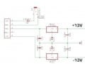
here is a circuit i have done, its one of them buck converters you can get from china which takes 9V DC to +/- 15V DC then i have regulated it so I get +/-13V DC the thing is i am pretty sure i dont connect the grounds to the ground input. Don't i need to have 'virtual ground', somewhere where there can be 0V potential?
if so what capacitors/other components do i need to connect this to make it work.


dl324

Joined Mar 30, 2015
18,326
You need to connect ground for the two regulators to ground for the +/-15V supplies.

What is the purpose of the zener diodes? If you're trying to raise the output voltage of the regulators, you can use a signal diode. The diodes are backwards if that was the intent.
EDIT: Was trying to increase regulator voltage to 13V. Probably can't get there due to regulator dropout voltage.

What is the purpose of D9? Are you worried about reverse polarity?

What is GND2?

The Moderators prefer for you to post files on this site so members don't have to deal with broken links in the future.
Capture.jpg
EDIT: add circuit in question.
 
Last edited:

AlbertHall

Joined Jun 4, 2014
12,625
Your circuit will
You need to connect ground for the two regulators to ground for the +/-15V supplies.

What is the purpose of the zener diodes? If you're trying to raise the output voltage of the regulators, you can use a signal diode. The diodes are backwards if that was the intent.

What is the purpose of D9? Are you worried about reverse polarity?

What is GND2?
"You need to connect ground for the two regulators to ground for the +/-15V supplies." - and the ground for the ±15V is GND2 and I agree.
The 5.1V zener diodes are to raise the output of the regulators from 8V to 13V and are connected correctly.
 

Thread Starter

drogheda1

Joined May 9, 2017
9
yea better to be safe from reverse polarity. the grounds can be connected like this but do they need to be seperate from the ground connected to that buck converter.

*gnd2 is just spare pin on the converter
 

Attachments

AlbertHall

Joined Jun 4, 2014
12,625
EDIT: Was trying to increase regulator voltage to 13V. Probably can't get there due to regulator dropout voltage.
The dropout voltage for the 7X08 regulators is specified as typically 2.0V at 1A so might get away with it, especially if using less than 1A.

Can you give us a link to buck converter you are using?
 

Thread Starter

drogheda1

Joined May 9, 2017
9
ive bradboarded this and it does work once all grounds are connected. if this was then put into a bipolar circuit requiring the +/-13V i dont think it would work as the voltages would not be right. ideally if there was a power module that exists with the following connections: a voltage input where you would put your positive and a common connection for the input ground, + and - voltage outs and a virtual ground for these to connect to.
 

crutschow

Joined Mar 14, 2008
38,503
ive bradboarded this and it does work once all grounds are connected. if this was then put into a bipolar circuit requiring the +/-13V i dont think it would work as the voltages would not be right. ideally if there was a power module that exists with the following connections: a voltage input where you would put your positive and a common connection for the input ground, + and - voltage outs and a virtual ground for these to connect to.
If it gives you ±15V out with respect to its ground than you can put it in any circuit with all grounds connected.
Why do you think you need a "virtual ground"?
 
Top