Grounding of multiple power sources together

Thread Starter

Zackoule

Joined Nov 17, 2019
3
Hi ,
I am trying to make the following :
24VAC power supply + 0-10 VDC power supply together in one enclosure.
I want them to have a common ground , the 0-10VDC and the 24VAC.

I am an electrician and in my line of work it is not uncommon to see a few power sources in one cabinet all referenced to ground Ac and DC.

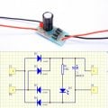
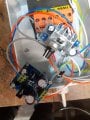
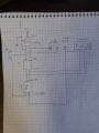
I tried making this unit and kept on frying the electronics... I will post some pics and a schematic.

I would love to understand what I am doing wrong.

Thanks
 

Attachments

ElectricSpidey

Joined Dec 2, 2017
2,779
Looks to me like the ground connection (why not) is bypassing the negative output from the first ac to dc converter and applying positive voltage to the negative side of the second dc unit.

Also placing the primary and secondary windings to earth ground is a no-no.
You should ground only the case of the transformer.
Of course I could be reading your schematic incorrectly.
 
Last edited:

Thread Starter

Zackoule

Joined Nov 17, 2019
3
Hi ,
What would you recommend ? The circuit works fine without the "why not " ground.
The problem is I would like a common for the DC and AC . What can I do ?
I tried all kinds of variations for the grounding but none with success
 

dendad

Joined Feb 20, 2016
4,476
Do you have the circuit of the power supply?
It looks like a +/- supply board to me.
And if you want to use the 24VAC as a separate supply, that can be a problem as whatever you connect that to may ground one side or the other.
Please post full details of the devices you want to connect, along with the circuit or connection info of the PCB you are showing in the photo.
 

DbLoud120

Joined May 26, 2014
91
If you are using a bridge circuit for ac to dc such as what I have attached, connecting J2 to J4 with a ground wire you are bypassing D3 with a wire instead of a diode.
 

Attachments

dendad

Joined Feb 20, 2016
4,476
You cannot common the AC and DC to ground, unless you run only half wave rectifiers. Otherwise, the other half wave will short out.

halfwave.jpg
But, half wave rectifiers may introduce hum on larger loads.

Or use a center tapped transformer with the center tap as the common point.
Really, more details are needed of the boards you are trying to use, and your end application.
I have run the above circuit in some industrial applications, but I would prefer a separate 24VAC winding to the one running the DC supplies.
 
Last edited:

Thread Starter

Zackoule

Joined Nov 17, 2019
3
Hi ,
Thanks for the replies.
Truth is I do not have enough info or knowledge to share more than the photos.
They are just some parts I had laying around.
One is a ac to dc and one is a variable dc out even though it does have a diode bridge after input so it can handle ac I think.
I think what I will do is add a proper 230V to 12VDC before the variable 0-12vdc unit.
I am sure that if I ground the 12VDC power supply it will work and not cause trouble

What I am trying to do is make a test unit for HVAC actuators who run on 24VAC with a 0-10VDC actuating signal.

Thanks for the help
 
Top