grounding metal project case - 2 wire external DC power supply?

Thread Starter

epicycloid

Joined Jan 27, 2012
4
Longtime lurker / reader / hobbyist... first actual post.

I am working on a project using Pololu DRV8825 stepper motor drivers, enclosed in a metal project box, powered by a 2-wire external 12V DC "soap-on-a-rope" type power supply. The installation involves a lathe that has a high speed urethane belt driving a cutter, which is independent of the stepper controller, which is driving the spindle at slow speeds.

Twice now I have had a DRV8825 driver fail, in a similar fashion. It is leading me to think that there might be an issue with the urethane belt, which seems to generate a lot of static electricity. Perhaps being near the belt and touching the project enclosure allows the static electricity to fry the DRV8825 stepper driver somehow?

My question is, is there some proper way to ground a metal project enclosure, when the only wires coming to it are the + & - from the DC power supply? (Meanwell GS60A12-P1J) Or is there some other "best practice" to protect a circuit and enclosure in a potentially high-static environment, where the only power is from the DC supply?

I did try to connect the negative / ground of the DC side, to the case as an experiment, but same results. The failure mode for the DRV8825 seems to affect the step-size portion of the driver, e.g. the driver randomly goes into a different microstepping mode from the way it was hardwired (before it quits altogether).

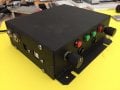
A pic is attached of the simple enclosure, with power jack for the DC supply, USB port (used only when programming), and two motor jacks. Buttons for each motor are "run", "stop" and "direction", along with an encoder to vary the speed. Nothing really complicated. I don't have a schematic, as this is just simple breadboard point-to-point wiring between a Teensy 3.2, a buck converter, conditioning capacitors and the stepper drivers.

Any insights appreciated, thanks.
 

Attachments

MaxHeadRoom

Joined Jul 18, 2013
28,688
Are you sure your conclusion of static is correct and not excessive loading?
Or incorrect maintaining of the correct motor current by the drive?
Max.
 

Thread Starter

epicycloid

Joined Jan 27, 2012
4
Are you sure your conclusion of static is correct and not excessive loading?
Or incorrect maintaining of the correct motor current by the drive?
Max.
Thanks for the suggestions / questions.

No, I am not sure that static is the cause, more suspicious that it could be. I am trying to troubleshoot the setup and identify the problem / cause. Static and grounding seemed like possible candidates (and I don't know what the best practice is for the original grounding / static dissipation question either).

The setup ran for numerous days with no issues. The load didn't change (same lathe, same usage). The motor current stayed the same as far as I know, e.g. I didn't alter the driver, and I measured & set it for the first one, and then for the replacement driver when the first failed.

After running for a few days, I moved the lathe to a new location, and had a failure within a few minutes running it. I swapped in a new driver board (socketed), set the current limit for the stepper motor, and ran that. It also failed after a just a few minutes, with the same behavior, seemingly losing its microstepping setting before completely failing. I had the microstepping set with a jumper to 1/8th steps. When the drivers failed they acted like they had been set to 1/32nd steps, e.g. the motor slowed way down, as the pulse train stayed constant but the microstepping was increased by 4x.

I have heatsinks installed on the driver chips. I'm only using a NEMA 23 motor rated at 1.5A, while the driver, with heatsink, is rated up to 2.2A. My pyrometer had not indicated any issues with heat during the initial testing (many hours). I've done other work with drivers that overheated, and hit their current limits, so I'm somewhat familiar with that failure mode, and this was very different.

Unless anyone has some better troubleshooting suggestion, I'm planning to move the setup to the bench, and just try with another new driver, and without the static-inducing cutter. See if that works, then re-introduce the cutter (static) and see if that kills it again.
 

shortbus

Joined Sep 30, 2009
10,045
Wouldn't a simple wire from the lathe frame to the driver case do what you want? This would put all of the items in question at the same voltage potential.
 

Kjeldgaard

Joined Apr 7, 2016
476
These lathes has reminiscent of a Van de Graaff generator.

My suggestion is also something with wires, but as potential equalization.

And that is to connect all major metal parts electrically. Here it's the main spindle, X-Y table, the cutting motor casing and the controller casing.
 

shortbus

Joined Sep 30, 2009
10,045
Thanks. That might work, if the lathe was made of metal, but it's not: MDF rose engine.

And here is a link to the belting driven cutter that has the potential to induce the static I referred to: Build and Overhead Drive.
Your link to the rose engine shows the difference in static build up I think. It shows the belts a polyurethane(PU) not neoprene. Where I worked at one time I ran a pantagraph engraver pretty regularly, it originally had PU belts from the factory, when they wore out they were replace with neoprene "O" rings because they were cheaper. No static shocks using the PU belts but with the neoprene you needed to first touch the running machine with a piece of metal in your hand to keep from getting shocked.

To what Kjeldgaard, said a metal brush close to the belt(s) but not touching them with a wire from the brush to ground should also reduce or eliminate the static.
 

Thread Starter

epicycloid

Joined Jan 27, 2012
4
Your link to the rose engine shows the difference in static build up I think. It shows the belts a polyurethane(PU) not neoprene. Where I worked at one time I ran a pantagraph engraver pretty regularly, it originally had PU belts from the factory, when they wore out they were replace with neoprene "O" rings because they were cheaper. No static shocks using the PU belts but with the neoprene you needed to first touch the running machine with a piece of metal in your hand to keep from getting shocked.

To what Kjeldgaard, said a metal brush close to the belt(s) but not touching them with a wire from the brush to ground should also reduce or eliminate the static.
Thanks. Very similar idea to running a pantograph, same issues.

That said, the belt composition varies (and won't always be my choosing, e.g. someone else may choose neoprene on their machine), but the urethane belt I'm currently using, is definitely generating detectable static. I was just using a non-stepper version of the lathe yesterday, and can confirm some static being generated. I think a grounding brush for the belting is a simple thing to make and test, and probably easier to ground than the stepper enclosure (since I do think the DC motor body has a ground wire).

So the question is still, for something like both of these motors, the stepper in particular, and other variable speed DC motors, what do I actually use for a ground wire? Is the negative side of a DC power supply sufficient for a return path to ground? Or do I need to cobble together some (dedicated) wire / grounding strap back to the actual AC source, and tie into the ground pin of a 3-prong outlet? What is the typical "best practice" for these types of uses where equipment grounding is needed, downstream from a 2-wire DC power supply?
 

MaxHeadRoom

Joined Jul 18, 2013
28,688
So the question is still, for something like both of these motors, the stepper in particular, and other variable speed DC motors, what do I actually use for a ground wire? Is the negative side of a DC power supply sufficient for a return path to ground? Or do I need to cobble together some (dedicated) wire / grounding strap back to the actual AC source, and tie into the ground pin of a 3-prong outlet? What is the typical "best practice" for these types of uses where equipment grounding is needed, downstream from a 2-wire DC power supply?
You normally do not take a motor frame ground wire back to the DC -ve, especially where the DC supply is not referenced to earth ground, a motor frame ground should return to a service ground conductor, preferably there should be a star point ground set up for multiple motors etc. the service GND would be connected also.
Max.
 
Top