GPS NMEA antenna aiming tracker.

ericgibbs

Joined Jan 29, 2010
18,766
hi,
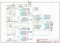
Are there 4 wires from your USB to RS232 adaptor.? +5V, 0V, TXD, RXD [+D, -D]
If you are not drawing current from the PC's USB port to power your project, the +5V can be left disconnected from the project.
The USB/RS232 0V must be connected to your project.
E
 

Thread Starter

camerart

Joined Feb 25, 2013
3,724
Hi Eric,

I use two adaptors, both plugged into USB sockets. 1/ has GND/TX connected to the PIC GND/RX and 2/has GND/RX connected to the PIC GND/TX. Only 1/ needs to be disconnected while switching on.

EDIT: Both adaptors show 3.4v at rest. Signals go 0V. This is only a slight problem while testing and injecting signals directly to the AZ an EL PICs. I just need to remember it, that's all.

Camerart.
 
Last edited:

Thread Starter

camerart

Joined Feb 25, 2013
3,724
Hi,

Update of the tracker PCB and CONTROL and AZIMUTH and ELEVATION programs.

AS EACH OF THE PROGRAMS CHANGE WITH DEVELOPMENT, I WILL UPDATE THEM HERE.

NOTE on the TRACKER CIRCUIT, 18F4520 LCD connections A and K should be reversed!

Camerart.
 

Attachments

Last edited:

Thread Starter

camerart

Joined Feb 25, 2013
3,724
Hi,

Just got the latest program(In post #565): 18F2431 AZ BRAKE 150216 1100 tmr0 L=0 H=0 5dband to work pretty well. Here's a link to a video: https://drive.google.com/file/d/0B_vJZLGyFK8DUW0wS1doOVFsTFE/view?usp=sharing

Once the input data is entered (e,g, A123E456) the 123 is extracted and used, as the AZIMUTH angle to aim towards. If it is outside the DEADBAND then in moves in the calculated direction, till it is within the DEADBAND then the motor brake is applied. If inertia takes it to the other side of the DEADBAND then it bounces back into the DEADBAND. The TMR0 time L0-255 H0-255 is the time for the brake before getting the next DATA input.
Check for errors before connecting to a HBRIDGE:)

Camerart.
 
Last edited:

ericgibbs

Joined Jan 29, 2010
18,766
hi,
This is what I see, ref image
E

EDIT:
It plays OK on your PM'd link ,, it now also plays OK on your posted link.
E
 

Attachments

Last edited:

Thread Starter

camerart

Joined Feb 25, 2013
3,724
Hi,
I've updated a couple of files in POST#565. 18F4520 and 18F2431 AZIMUTH now work ok.
Camerart.
 
Last edited:

Thread Starter

camerart

Joined Feb 25, 2013
3,724
Hi,
I've added an 18F2431 ELEVATION program, that works in test rig.
Next check everything and fit it in the TRACKER:)
C.
 

Thread Starter

camerart

Joined Feb 25, 2013
3,724
Hi,
I've just updated the 18F4520, 18f2431files in post #565.
The 18F4520 shows A360E??? when simulating it with my terminal (Teraterm).
When testing the 18F4520 and ELEVATION 18F2431 (Only) in circuit, the Elevation moves upward180degrees and oscillates.
I'm sure there isn't much wrong, and I'm still trying to find errors.

I've added the Teraterm files that I use to simulate NMEA sentences coming into the tracker, in case someone wants to try, but these need changing to suit your filing system. Also at the bottom of of the 18F4520 program.

The 18F4520 now needs it's button (Added after the circuit design) pressing,so that the tracker BASE location is read from the REMOTE CRAFT while it is next to the Tracker, once shown on LCD, release button and as the REMOTE moves away, it will start calculating. [The button is reverse in simulation, due to pull up resistor] I switch motors on after the REMOTE is away from the tracker.

Camerart.
 
Last edited:
Top