GPS NMEA antenna aiming tracker.

Thread Starter

camerart

Joined Feb 25, 2013
3,838
hi C,
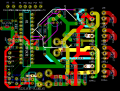
Looks OK, recheck using my coloured copy.
E
EDIT:
You have not removed those Gate shorts.????
Hi E,

Good, thanks.

I'm not sure about the gate shorts! It is the correct pad for the mosfets. When I print for the circuit, they aren't there, so the circuit won't have shorts. Perhaps there are pads in online libraries without them?

C.
 

Thread Starter

camerart

Joined Feb 25, 2013
3,838
Hi Eric,

I should finish the 18F2431 motor drive circuits today. I have all of your past programs. Can you suggest which one would be best to use for a circuit test please. I'll add fuses to the power section.

Cheers, Eric.
 

ericgibbs

Joined Jan 29, 2010
21,455
hi C,
As far as I can see I have not posted a PWM program.??
These two basic programs were for demo only, written for the 18F4520, you will to convert them to run on a 18F2431.

Eric
 

Attachments

ericgibbs

Joined Jan 29, 2010
21,455
hi E,
Started converting to 18F2341, get an error message that Oshonsoft does not have the ADC module support.!
Oshonsoft is getting very frustrating, it means you cannot create a hex file using Basic when it contains a ADC function, at least you would expect Oshonsoft to warn you
that the code for the ADC would not be created and compile the remainder of the code.
The only fix I can suggest is that you remove the Basic statements for the ADC and write a ASM subroutine for the ADC operation.

E
 

Thread Starter

camerart

Joined Feb 25, 2013
3,838
hi E,
Started converting to 18F2341, get an error message that Oshonsoft does not have the ADC module support.!
Oshonsoft is getting very frustrating, it means you cannot create a hex file using Basic when it contains a ADC function, at least you would expect Oshonsoft to warn you
that the code for the ADC would not be created and compile the remainder of the code.
The only fix I can suggest is that you remove the Basic statements for the ADC and write a ASM subroutine for the ADC operation.

E
Hi E,

I'm sure the 18F2341 is a typo, should be 18F2431.

I struggle with Oshonsoft, so for me to write an ASM subroutine is impossible:(

As the ADC won't be used in the finished program, how about a PWM output that starts at motor STOP, then goes forward, slowly ramping up the speed, then similar in reverse? (LCD not necessary)

C.
 

ericgibbs

Joined Jan 29, 2010
21,455
hi,
Does your PCB have a socket for the PIC, ie: not soldered in.?

If yes, then we could use a another type of PIC for the PWM test , what other types of 28 pin PICs do you have.?

E,
yes a typo
 

Thread Starter

camerart

Joined Feb 25, 2013
3,838
hi,
Does your PCB have a socket for the PIC, ie: not soldered in.?

If yes, then we could use a another type of PIC for the PWM test , what other types of 28 pin PICs do you have.?

E,
yes a typo
Hi E,

Yes, socket.

I have 16F886 pics. Good idea.

C.
 

ericgibbs

Joined Jan 29, 2010
21,455
hi,
Try this PWM Oshonsoft Basic program for the 16F886.
Its set for simulation for you to try before programming a PIC.
As its only for testing, set the PWM rate to zero, using AN0, before changing forward/reverse with PORTA.3
The PWM base frequency is ~9600Hz, if this is audibly noisy, use a higher PWM value.

E
 

Attachments

Thread Starter

camerart

Joined Feb 25, 2013
3,838
hi,
Try this PWM Oshonsoft Basic program for the 16F886.
Its set for simulation for you to try before programming a PIC.
As its only for testing, set the PWM rate to zero, using AN0, before changing forward/reverse with PORTA.3
The PWM base frequency is ~9600Hz, if this is audibly noisy, use a higher PWM value.

E
Ok Eric,

Thank you.

C.
hi,
Try this PWM Oshonsoft Basic program for the 16F886.
Its set for simulation for you to try before programming a PIC.
As its only for testing, set the PWM rate to zero, using AN0, before changing forward/reverse with PORTA.3
The PWM base frequency is ~9600Hz, if this is audibly noisy, use a higher PWM value.

E
Hi Eric,

Your PWM program is simulating ok (without 'Line 27: Unused declaration: Dim vadc0 As Byte')
Now to try it on the tracker.

C
P.S. Thanks for good program commenting.
 

Thread Starter

camerart

Joined Feb 25, 2013
3,838
hi,
Ref your PM look at this edited diagram for linking in order to use the 16F886

E
I switch OFF the error reporting on Oshonsoft
Hi E,

Yes, I could do this instead of my suggestion. This means that both F/R mosfet sets are switching. Safer than my method I think!

C
 

ericgibbs

Joined Jan 29, 2010
21,455
hi C,
The 16F886 Basic test PWM program is working OK in hardware, varying the light intensity of a pair of LED's, however, it appears that when using both CCP's [pins 12 & 13] for the PWM signal, Forward or Reverse, there is an continuous unwanted 1 uSec pulse on the unused PWM pin, it occurs on the high going edge of the PWM pulse on the other pin.

I have sent Vladimir at Oshonsoft a Bug Report, I will let you know his reply.

Eric
 

Thread Starter

camerart

Joined Feb 25, 2013
3,838
hi C,
The 16F886 Basic test PWM program is working OK in hardware, varying the light intensity of a pair of LED's, however, it appears that when using both CCP's [pins 12 & 13] for the PWM signal, Forward or Reverse, there is an continuous unwanted 1 uSec pulse on the unused PWM pin, it occurs on the high going edge of the PWM pulse on the other pin.

I have sent Vladimir at Oshonsoft a Bug Report, I will let you know his reply.

Eric
Hi E,

The circuit is working with 16F886 with PWM disconnected from Hbridge. The PWM works ok on both channels (Apart from the problem you outline) The motor turns both directions with inputs to 0V and 5V in turn.

C.
 

ericgibbs

Joined Jan 29, 2010
21,455
hi,
You could, while we are waiting for Vlad, remove the wires from say pin #12 and connect them to 0V.[ so the 100R and 1K that go to pin 12, take them off 12 and connect them to 0V, so pin 12 is not connected]

Keep the pin #13 components connected as normal to the ends of one pair of 1k and 100R that go to the FET and 2N2222

Insert your programmed 16F866 using the test program I posted, you should then be able to control the motor speed in one direction.

If that works OK, change over the connections as described above and the motor should controllable in the other direction.
E
 

ericgibbs

Joined Jan 29, 2010
21,455
hi C,
The problem was with the compiler for the PWMduty x, 0, it was Setting the lower LSB bits instead of Re-setting them, so the OFF channel was outputting a 1uSc pulse.

Try this Basic/Asm hybrid, it works OK with LED intensity and Scope check.
Let me know how it goes.;)
E
Code:
Define CONFIG = 0x28e4
Define CONFIG2 = 0x3eff

'16F886  PWM 16F886 P3 Test 221014.V1

'Uses PORTC.2 as CCP1 [pwm1] Forward
'PORTC,1 as CCP2 [pwm2] Reverse
'PORTA,3 0= Forward ,  1 = Reverse

'PORTA,0 is AN0 analog, PWM duty, 0 thru 255 , for 0V thru +5Vin

'NOTE:  while testing Adjust AN0 rate to ZERO BEFORE changing Direction with PORTA.3
'Define SIMULATION_WAITMS_VALUE = 1  'else 0 for PIC
'When running in Oshonsoft Sim
'to view PWM use Scope, Normal , Settings, display width 1000
'to check use Hardware UART

ADCON0 = %01000001
ADCON1 = %00000000
ANSEL = %00000001
CM1CON0 = 0
OSCCON = %01110001  'internal 8Mhz clock

Dim duty1 As Byte
Dim duty2 As Byte
Dim pwm1 As Byte
Dim pwm2 As Byte

TRISA = %00011011
TRISB = %00001111
TRISC = %10001001

'assign PWM pins
PWMon 1, 8  'RC1 CCP1, Mode at 8MHz at 7812Hz, to change this look at the Manual Tables
PWMon 2, 8  'RC2 CCP2

'testing only
main:

If PORTA.3 = 0 Then
''PWMduty 2, 0
ASM:        bcf CCP2CON,DC2B0
ASM:        bcf ccp2con,dc2b1
ASM:        movlw 0x00
ASM:        movwf ccpr2l
Adcin 0, duty1
PWMduty 1, duty1
Endif

If PORTA.3 = 1 Then
''PWMduty 1, 0
ASM:        bcf CCP1CON,DC1B0
ASM:        bcf ccp1con,dc1b1
ASM:        movlw 0x00
ASM:        movwf ccpr1l

Adcin 0, duty1
PWMduty 2, duty1
Endif

Goto main
End
 

Attachments

Last edited:

Thread Starter

camerart

Joined Feb 25, 2013
3,838
hi,
You could, while we are waiting for Vlad, remove the wires from say pin #12 and connect them to 0V.[ so the 100R and 1K that go to pin 12, take them off 12 and connect them to 0V, so pin 12 is not connected]

Keep the pin #13 components connected as normal to the ends of one pair of 1k and 100R that go to the FET and 2N2222

Insert your programmed 16F866 using the test program I posted, you should then be able to control the motor speed in one direction.

If that works OK, change over the connections as described above and the motor should controllable in the other direction.
E
Hi E,

Yes, That works ok.

C
 
Top