Good high speed transistors for smps

Thread Starter

uraniumhexoflorite

Joined Oct 23, 2016
216
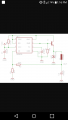
I'm working on an SMPS using an mc34063a and I'm worried that the transistor I'm using (TIP110) may be lowering the output current capability due to low switching speed. What are some transistors they can switch at a higher speed that I could use instead? Thanks. :)
 

DickCappels

Joined Aug 21, 2008
10,187
The '3406 was intended to drive a bipolar transistor. To get good performance with a MOSFET parts need to be added to the drive circuit. Since the TIP110 is a Darlington it won't turn off very quickly and will have a high saturation voltage. Going with a "regular" bipolar transistor is likely your best bet.

Please tell us what configuration you are using, the voltages, max current, frequency, etc. A schematic would be very helpful here. then we can figure out what an appropriate output transistor would be.
 

Thread Starter

uraniumhexoflorite

Joined Oct 23, 2016
216
Input voltage is 12 v output voltage is 5 v 220 microhenry inductor. Ive heard that BJTs are faster than MOSFETs, but I just wanted to confirm that this is correct.
 

dl324

Joined Mar 30, 2015
16,943
Circuit is a standard mc34063a step down using an external npn transistor
Well, the "standard" schematic doesn't give component values or input/output voltages, supply current, output current,...

Since you're being so stubborn about it, here's the generic schematic for the benefit of others:
upload_2017-3-22_8-40-7.png
 

DickCappels

Joined Aug 21, 2008
10,187
If you tell us the load current one of us might be able to suggest a good transistor to you.

Because MOSFETs have high input capacitance and drop a lot of voltage when used as a source follower, in the circuit you have shown, a bipolar would give results superior to a MOSFET.

One thing that often causes power supplies using the MC34063 to output less current than expected is that the inductor has too high of a resistance for the application. What is the resistance of your inductor (and what is your load current)?
 

crutschow

Joined Mar 14, 2008
34,464
Heres the basic schematic. All I needed was to know what type of transistor switches the fastest.
A MOSFET switches faster but will not work directly in that circuit, since MOSFETs require several volts Vgs to turn on and, as a source-follower in that circuit, the voltage drop across it would be equal to that Vgs voltage.

You could use a P-MOSFET instead but you would need an inverting driver, such as below, which uses the six CMOS inverter gates in one CD4049 connected in parallel to provide a low-impedance buffer to drive the high MOSFET gate capacitance.

The In terminal would be connected to pin 2 of the mc34063a, and the Out terminal goes to the P-MOSFET gate.

Select a P-MOSFET with less than 100mΩ ON resistance, and a low gate charge for fastest switching.

upload_2017-3-23_9-22-52.png
 

RichardO

Joined May 4, 2013
2,270
A MOSFET switches faster but will not work directly in that circuit, since MOSFETs require several volts Vgs to turn on and, as a source-follower in that circuit, the voltage drop across it would be equal to that Vgs voltage.

You could use a P-MOSFET instead but you would need an inverting driver, such as below, which uses the six CMOS inverter gates in one CD4049 connected in parallel to provide a low-impedance buffer to drive the high MOSFET gate capacitance.

The In terminal would be connected to pin 2 of the mc34063a, and the Out terminal goes to the P-MOSFET gate.

Select a P-MOSFET with less than 100mΩ ON resistance, and a low gate charge for fastest switching.

View attachment 123159
He can use a PNP or possibly a P channel MOS_FET as shown in figure 9 of the attached data sheet.
 

Attachments

crutschow

Joined Mar 14, 2008
34,464
I heard of someone using a PFET with the mc34063a, but i dont have any pfets and cant find any in the right package (TO-92 or TO-220) on amazon.
Can you order from DigiKey or Mouser?
They have hundreds to pick from.
Where are you located?

Yes, I see you can use a P-MOSFET without the driver I suggested.
Connect a 100 ohm resistor between the P-MOSFET source and drain (with source to +12V and drain to inductor).
Connect pins 1 and 8 to the MOSFET gate.
Connect pin 2 to ground.

It's similar to this with the P-MOSFET replacing the PNP (the resistor in series with the base is not needed with a MOSFET).
upload_2017-3-23_12-5-4.png
 

Papabravo

Joined Feb 24, 2006
21,227
Heres the basic schematic. All I needed was to know what type of transistor switches the fastest.
That is manifestly NOT what you need. What you need is to understand what you are doing and stop listening to your "little firends". But hey, you're stuck in drive and hell bent on putting the pedal to the metal -- so be my guest.
 
Top