 Facebook
 Google
 GitHub
 Linkedin
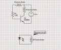
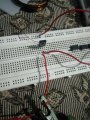
The aim to design a circuit to glow a 3w led wirelessly.The circuit that i followed is given below.Success was also acheived was able to transmit upto 6-8 cms.
Well i know the principles involved,DC into converted to a pseudo AC which generates flux in transmitter coil and the receiver catches those field lines to produce current in second coil.What i cant get is how the transistor(BD139) that i used is convertind that DC to a pulsating DC/Pseudo AC ? Any help regarding how the transistor is behaving in the circuit is appreciated.
Well i know the principles involved,DC into converted to a pseudo AC which generates flux in transmitter coil and the receiver catches those field lines to produce current in second coil.What i cant get is how the transistor(BD139) that i used is convertind that DC to a pulsating DC/Pseudo AC ? Any help regarding how the transistor is behaving in the circuit is appreciated.
Attachments
-
 42.9 KB Views: 37
 -
 303.6 KB Views: 32
 -
 351.8 KB Views: 32


