Facebook
 Google
 GitHub
 Linkedin
Good morning guys, this is my first post here. I have to prepare a project for a university exam and I'd like to build a "sample and hold" circuit. I'm almost a total newbie in this field (I've only studied this stuff on books, never did anything practical), so I did some research and came up with some links:
http://www.emagtech.com/wiki/index....ts#Building_an_Op-Amp_Sample-And-Hold_Circuit
https://www.electronicshub.org/sample-and-hold-circuit/
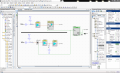
The first one looks promising, it shows the expected result after simulating the circuit using a computer (PSpice perhaps?) and that's what I'd like to build. However I've got a few of questions about the feasibility of this idea.
1) That website says I must use 2 AD711 op-amps, but I only have access to the classical 741 op-amp. Would the circuit still work with those?
2) I've read somewhere else (perhaps in the second link I've listed) that the capacitor must be electrolytic, in order for the leakage current to be small. Now, I barely know what a leakage current is, but the actual question is: would a ceramic capacitor work? Because I've asked the guy who runs my university's electronics lab to give me a 1 nF capacitor and he gave me a ceramic one. I'll have to check if he's got an electrolytic one, if it's strictly needed.
3) How the hell do I generate the control voltage (VCTRL in the second link), which should be a square wave, if I'm not wrong? I was thinking of using an Arduino board (not sure about how to do it, but it should be doable), but would it work?
I mean, the goal is that I connect an oscilloscope to the input and the output of the circuit and I'd like to see something similar to this: http://www.emagtech.com/wiki/index.php/File:MixTUT4_12.png
Do you think it's possible to do what I want, given these conditions?
Thanks in advance for your help!
P.S. I'll surely come up with more questions later, this is it for now. Thanks!
http://www.emagtech.com/wiki/index....ts#Building_an_Op-Amp_Sample-And-Hold_Circuit
https://www.electronicshub.org/sample-and-hold-circuit/
The first one looks promising, it shows the expected result after simulating the circuit using a computer (PSpice perhaps?) and that's what I'd like to build. However I've got a few of questions about the feasibility of this idea.
1) That website says I must use 2 AD711 op-amps, but I only have access to the classical 741 op-amp. Would the circuit still work with those?
2) I've read somewhere else (perhaps in the second link I've listed) that the capacitor must be electrolytic, in order for the leakage current to be small. Now, I barely know what a leakage current is, but the actual question is: would a ceramic capacitor work? Because I've asked the guy who runs my university's electronics lab to give me a 1 nF capacitor and he gave me a ceramic one. I'll have to check if he's got an electrolytic one, if it's strictly needed.
3) How the hell do I generate the control voltage (VCTRL in the second link), which should be a square wave, if I'm not wrong? I was thinking of using an Arduino board (not sure about how to do it, but it should be doable), but would it work?
I mean, the goal is that I connect an oscilloscope to the input and the output of the circuit and I'd like to see something similar to this: http://www.emagtech.com/wiki/index.php/File:MixTUT4_12.png
Do you think it's possible to do what I want, given these conditions?
Thanks in advance for your help!
P.S. I'll surely come up with more questions later, this is it for now. Thanks!