Facebook
 Google
 GitHub
 Linkedin
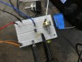
I have no idea why 13.6 gets back to the opti but not back to the Arduino when I feed it directly.That seems strange because I'm trying to figure out why you were reading 13.6 volts on the fan wire when we reversed the collector and emitter connections on the opto back in post #31. That voltage had to come from somewhere.
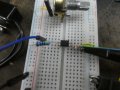
Getting an Opticoupler to work.
- Thread starter MB107
- Start date