Get data from car fuel gauge 12V to Arduino 5V

Thread Starter

vonjyandriah

Joined Feb 3, 2020
5
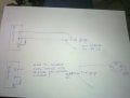
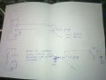
Hello everyone, I am working on a small project consisting in recovering as much as possible the data of my car which is still old for its age (Peugeot 305 year 1985), so I am looking for a way to combine my project with the existing system in the car . My problem is that I am trying to recover the data coming from the fuel gauge, which during my tests was powered by the VCC 5volt of my arduino, but currently wanting combined with the original circuit, I face a voltage of 12v at the level of the gauge, so I ask a little help from you to move forward, I think of using a transistor but concretely I am afraid of burning my arduino, thank you
 
There is all sorts of fuel gauge weirdnesses out there in auto and boat land. generally, there is a min and max resistance and a direction. The similarity ends there. You also have irregular shaped tanks.

Back in 1968, I remember a meter and a pulsed voltage regulator.

In 1982, the regulator was pulsed as well, but there was lots of oil in the guage to dampen it heavily. That also had a self-heating thermister to detect empty.

then there are totally bizzare fuel guages.

there are some devices out there that will convert sending element resistance values.
 

Thread Starter

vonjyandriah

Joined Feb 3, 2020
5
[QUOTE = "ericgibbs, message: 1474207, membre: 73660"]
salut v,
Bienvenue chez AAC.
Vous pouvez utiliser un régulateur 5V pour réduire le 12V à 5V, par exemple: 7805 ou 78L05.
E
[/CITATION]
merci pour votre retour, le problème c'est que ce n'est pas la tension qui doit être réduite à 5V mais le signal carrément, donc si j'utilise lm7805 pour ça, je pense que ça va déformer mes données
 

Thread Starter

vonjyandriah

Joined Feb 3, 2020
5
There is all sorts of fuel gauge weirdnesses out there in auto and boat land. generally, there is a min and max resistance and a direction. The similarity ends there. You also have irregular shaped tanks.

Back in 1968, I remember a meter and a pulsed voltage regulator.

In 1982, the regulator was pulsed as well, but there was lots of oil in the guage to dampen it heavily. That also had a self-heating thermister to detect empty.

then there are totally bizzare fuel guages.

there are some devices out there that will convert sending element resistance values.
yes, the minimum value is 89Ohm and the maximum value is 1620Ohm, these values have already been inserted and coded on arduino, no problem, my current problem is to be able to connect my arduino which uses 5V or that the 12v probe generates
 

ericgibbs

Joined Jan 29, 2010
18,766
hi v,
When you did your Arduino tests did you notice that the response of the sender circuit is non linear.? ie sensor resistance versus voltage output.
If yes, are you correcting the response in the Arduino program.?

E
BTW: Over the years we have posted a number of tank gauge sender circuits, are you able to purchase OPA's , components OK.?
 

MrSoftware

Joined Oct 29, 2013
2,188
The most basic way to shift a 12v analog fuel gauge down to the 5v range is with a voltage divider.

https://learn.sparkfun.com/tutorials/voltage-dividers/all

Some experimentation might be needed to nail down the values, but here's a quick guess as to some values that might work. Assuming your highest voltage can be 14v (when the motor is running), and you want to go up to only 4.5v at the arduino to give you some safety margin, you can try a 50k and 24k resistor for your divider. This should provide enough current for the ADC on the arduino to work, and limit current enough that your regular gauge won't be affected. Also put a 5v zener between the arduino input pin and ground. This way if the voltage gets above 5v, the zener will short it to ground, saving your arduino.

Using this calculator: http://www.ohmslawcalculator.com/voltage-divider-calculator

1580821839497.png
 

MisterBill2

Joined Jan 23, 2018
18,167
You will have an interesting time with looking at the fuel level signal because in addition to being powered by a noisy vehicle electrical supply there is probably an electric fuel pump in the tank. So there will probably be a great deal of noise coupled into the signal from the tank sender.
Since this is a slowly changing voltage you can use a longer time constant filter circuit to reduce any incoming noise spikes. I also recommend having an op-amp circuit, perhaps with a gain of 0ne, following the filter and voltage divider, so that if there is damage from something it will be a cheap opamp destroyed on not the big expense item. You also need to use a high enough series resistance to avoid causing the existing fuel gage to be in error.
 

MrSoftware

Joined Oct 29, 2013
2,188
Just over sample and average the ADC readings. If you're already using an arduino, might as well put the solution in the software. ;)
 

MisterBill2

Joined Jan 23, 2018
18,167
Just over sample and average the ADC readings. If you're already using an arduino, might as well put the solution in the software. ;)
Filtering the signal before it gets to the A/D is one way to protect it from random High voltage spikes. You can not surpress those spike that break ICs with any kind of software. I was, and am talking about actual transient events commonly found in automotive power systems, not little bits of noise.
 

MrSoftware

Joined Oct 29, 2013
2,188
Gotcha. A filter definitely would not hurt. Do you think it's worth buffering with an OpAmp, or would perhaps a series resistor and TVS diode to ground be good enough?
 

MisterBill2

Joined Jan 23, 2018
18,167
Gotcha. A filter definitely would not hurt. Do you think it's worth buffering with an OpAmp, or would perhaps a series resistor and TVS diode to ground be good enough?
Using an op-amp allows more filtering because it can make up for filter losses. I trust opamps more than TVS devices.
 

ericgibbs

Joined Jan 29, 2010
18,766
hi v,
This LTSpice sim shows two circuit options.
1. Constant current drive to the sensor, gives a fairly linear response for the ADC input [ a black line has been added as a linear reference]
2. Resistive divider, gives a non linear response.

To cope with the 12V thru 14V battery state, you could ADC sample the battery voltage and correct the sensor value in the program.

E
AAA 154 08.32.gif
 

MisterBill2

Joined Jan 23, 2018
18,167
hi v,
This LTSpice sim shows two circuit options.
1. Constant current drive to the sensor, gives a fairly linear response for the ADC input [ a black line has been added as a linear reference]
2. Resistive divider, gives a non linear response.

To cope with the 12V thru 14V battery state, you could ADC sample the battery voltage and correct the sensor value in the program.

E
View attachment 198329
The TS does not want to redesign the fuel gauge circuit of the vehicle, only to add a monitor point for the arduino to see the gauge signal without affecting the cluster fuel gauge reading. So while the circuit shown is good it is not at all what is needed.
 

ebeowulf17

Joined Aug 12, 2014
3,307
Here's my take on scaling the fuel sensor readings down to 5V. I know nothing at about fuel sensor wiring, so I'm taking the sketch from post 6 as the starting point. I had no idea what sort of resistance the gauge itself would have, so I just guessed.

The attached sim shows two approaches. One uses a voltage follower as a simple buffer and then uses a resistive divider to scale the voltage down to an acceptable range. The other uses three op amp stages (can all be in one 14 pin package, so circuit is much simpler than it looks) to make differential circuit which measures voltage across the sensor. This scales the output voltages across almost the entire ADC input range, instead of the smaller subset that the simpler circuit uses. This is probably the one I'd try first if it was my project.

Both of these circuits will read differently at 12V (car off) than at ~14.4V (car running) but I'm hoping that just having good readings when the car is actually running is good enough. Also, both circuits would benefit from at least a little input protection against the noise spikes mentioned above, but that just takes a few extra resistors and diodes. If you like one of the concepts below, we can draw an updated version with protections.

***EDIT: I just ran a few more version of this test with different resistance values for the gauge portion of the circuit. It turns out that makes a huge difference, not only in the specific component values you'd choose for scaling, but also in terms of which overall approach makes the most sense. If this were my project, I'd get some voltage readings across the sensor at various fuel levels and try to get a sense of which voltage span is more useful, the voltage between ground and the node I've labelled "V-gauge" or the voltage across the fuel sensor (between V-supply and V-gauge.) The way these voltages respond will depend on the nature of the fuel gauge itself, not just the fuel sensor. Only after getting some more real-world sensor data would I decide on the best approach. I think my earlier conclusions were premature.

fuel-gauge-monitor_02.PNG
 

Attachments

Last edited:
Comments:
Does your vehicle have any sort of voltage regulator? Many sensors in a vehicle are ratiometric meaning, readings are relative. Typically to mid supply.

Did you think about using a zero resistance ammeter type of circuit?

One caveot that may or may not be a problem is protection of voltages exceeding the supply voltage. This would happen if the arduino was unpowered and got a signal. Vcc at that point is zero. There are protection mechanisms that you can use.

Some gas gauges operate totally off the wall.

Some examples: https://www.aa1car.com/library/fuel_gauge_diagnosis.htm
 
Top