Generate 24VAC (support 1.5 amp draw) from 36-42VDC

dendad

Joined Feb 20, 2016
4,641
It still does not make sense!
You say you will use a power adapter anyway, so why not instead use a 24VAC transformer?
And if you are to use a power adapter, that indicated you have mains available.
You can get the 5VDC from the 24VAC, or use a small switch mode supply like a phone charger.
Why do you insist you have a size limit?
The transformer would replace the power adapter, and that is external.
There are quite a few 24VAC transformers available. (Ebay search)
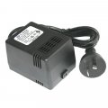
24VAC_36VA.jpg
24VAC_150VA.jpg

Why is something like this not suitable when a DC power brick is?
 

Thread Starter

Mahonroy

Joined Oct 21, 2014
417
To revive this thread... the two main reason why we can't go with an external 24VAC transformer is looks, and current capabilities. It also turns out we need at least 2 amps @ 24VAC, and there are no nice looking transformers with these specs.

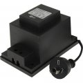
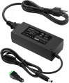
Everyone is happy with going with a laptop style power supply, such as a 36VDC, 3 amp power supply. These are also inexpensive, and look much better:
1651173825185.png

With that said, it looks like I could use this 36VDC for the "+" on the op-amp, and then I need to create an inverted power rail for the -36VDC for the "-" on the op-amp. With that, I should be able to generate a square or sine wave 24VAC signal right?
 

Thread Starter

Mahonroy

Joined Oct 21, 2014
417
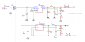
Could I use a circuit similar to this, only modified for +34V and -34V, and use that to generate the square wave / sinewave?
1651177435823.png
 

Thread Starter

Mahonroy

Joined Oct 21, 2014
417
Is this a decent way of accomplishing this? I've already mentioned numerous times, it has to be a 36-40VDC power input, absolutely no 24VAC transformer, and the device has to be small. Can we focus on the actual question and no more side tracking?
 

Ian0

Joined Aug 7, 2020
13,191
During the positive-going part of the waveform, the left side of the load connects to the positive supply and the right side connects to the negative supply.
During the negative-going part of the waveform, the right side of the load connects to the positive supply and the left side connects to the negative supply.
So the load sees an AC waveform, alternatively positive and negative.
 

Papabravo

Joined Feb 24, 2006
22,096
So a 24VAC signal looks like a sinewave with peak voltages of +34V and -34V. So where does the -34V come from if it doesn't use a negative rail?
If you knew about standard inverter circuits you would know that a full bridge configuration will reverse the polarity of the DC signal across the load mimicking the behavior of an AC source.
 

Papabravo

Joined Feb 24, 2006
22,096
So a 24VAC signal looks like a sinewave with peak voltages of +34V and -34V. So where does the -34V come from if it doesn't use a negative rail?
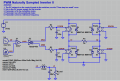
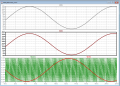
It took me a while to work up this proof of concept inverter using ideal switches, a reference sine wave and a sawtooth generator to sample the reference sinewave. This inverter uses a single DC supply without the need for a negative supply.
1651553363800.png
1651553452885.png
 

Thread Starter

Mahonroy

Joined Oct 21, 2014
417
It took me a while to work up this proof of concept inverter using ideal switches, a reference sine wave and a sawtooth generator to sample the reference sinewave. This inverter uses a single DC supply without the need for a negative supply.
View attachment 266345
View attachment 266346
Thanks a lot, this helps a lot. I have a few questions if you don't mind?

1. Regarding V1/{vdc}, is this 34VDC? Lets say hypothetically we were using an H-bridge to do a square wave 24VAC output. Would 34VDC not be the appropriate value to use here? Would you instead make a square wave out of 24vdc? (e.g. positive 24VDC, and negative 24VDC, 50% duty cycle)?

2. Regarding S1 through S4. I'm guessing these are actually mosfets, is that right? And "S13ON","S24ON", etc. is the gate of the mosfet?

3. The load, or in this case a sprinkler valve, would be connected between n1 and n2 is that right?

4. I am not following what is going on with U1 and U2 (and related U3 and U4), basically what I need to do to drive the mosfets in order to create a sinewave, rather than a square wave?

5. Am I misunderstanding the output, or is this output missing the negative voltages? It looks like a sinewave alternating between 36V and 0V, instead of 34V and negative 34V?

Thanks again for all of the help!
 

Thread Starter

Mahonroy

Joined Oct 21, 2014
417
During the positive-going part of the waveform, the left side of the load connects to the positive supply and the right side connects to the negative supply.
During the negative-going part of the waveform, the right side of the load connects to the positive supply and the left side connects to the negative supply.
So the load sees an AC waveform, alternatively positive and negative.
And speaking of these H-bridges, Can I use these H-bridge chip to accomplish this? If I wanted to do a square wave to approximate a 24VAC output, would I use 34V and negative 34V? Or would I use 24V and negative 24V?

These are the H-bridge chips I was looking at:
DRV8251DDAR
https://www.ti.com/lit/ds/slvsfz6/slvsfz6.pdf?ts=1651531694969

TB67H451FNG,EL
https://www.digikey.com/en/products/detail/toshiba-semiconductor-and-storage/TB67H451FNG-EL/11568781

Could I just alternate between forward and reverse on this chips? Then either enter the state of "Coast" or "Brake" for turning off?
 

Ian0

Joined Aug 7, 2020
13,191
These are the H-bridge chips I was looking at:
DRV8251DDAR
https://www.ti.com/lit/ds/slvsfz6/slvsfz6.pdf?ts=1651531694969

TB67H451FNG,EL
https://www.digikey.com/en/products/detail/toshiba-semiconductor-and-storage/TB67H451FNG-EL/11568781

Could I just alternate between forward and reverse on this chips? Then either enter the state of "Coast" or "Brake" for turning off?
Yes.

The solenoid valves are not going to be bothered whether they get a sinewave or a squarewave. Don't forget that the current is the integral of the voltage for an inductive load, so a squarewave voltage will give a trianglewave current, which is reasonably sinusoidal!
 

Thread Starter

Mahonroy

Joined Oct 21, 2014
417
Yes.

The solenoid valves are not going to be bothered whether they get a sinewave or a squarewave. Don't forget that the current is the integral of the voltage for an inductive load, so a squarewave voltage will give a trianglewave current, which is reasonably sinusoidal!
So would I provide the solenoid valves with 24V and negative 24V square wave? Or 34V and negative 34V square wave?
 

Ian0

Joined Aug 7, 2020
13,191
You can use either. If you use a higher voltage than 24V then you can reduce the mark/space ratio to get the right current.
 

Thread Starter

Mahonroy

Joined Oct 21, 2014
417
You can use either. If you use a higher voltage than 24V then you can reduce the mark/space ratio to get the right current.
Ok thanks for that info. Do you know how a multimeter set to AC voltage would read a 24V to negative 24V peak square wave? It seems like it should actually interpret it as 24VAC right?
 

Papabravo

Joined Feb 24, 2006
22,096
Thanks a lot, this helps a lot. I have a few questions if you don't mind?

1. Regarding V1/{vdc}, is this 34VDC? Lets say hypothetically we were using an H-bridge to do a square wave 24VAC output. Would 34VDC not be the appropriate value to use here? Would you instead make a square wave out of 24vdc? (e.g. positive 24VDC, and negative 24VDC, 50% duty cycle)?

2. Regarding S1 through S4. I'm guessing these are actually mosfets, is that right? And "S13ON","S24ON", etc. is the gate of the mosfet?

3. The load, or in this case a sprinkler valve, would be connected between n1 and n2 is that right?

4. I am not following what is going on with U1 and U2 (and related U3 and U4), basically what I need to do to drive the mosfets in order to create a sinewave, rather than a square wave?

5. Am I misunderstanding the output, or is this output missing the negative voltages? It looks like a sinewave alternating between 36V and 0V, instead of 34V and negative 34V?

Thanks again for all of the help!
1. In the title to the post you indicated that Vdc could have any value between 36 and 42 Volts. I made it a parameter so you could easily change it, or step it, to see the results of changing it. The value of Vdc works in conjunction with the amplitude modulation index \( m_{a} \). In this simulation it is set to 0.96 and the RMS value of the output is just about 24 VAC. It does have a DC offset as you can see.

2. I usually begin an investigation of this type using "ideal" switches, inoder to facilitate understanding the underlying algorithms. To put the concept into practice you would use an "actual" semiconductor switch, which could be a BJT, MOSFET, IGBT, SiCFET and so on. You are correct in that S13ON and S24ON would control the gate of an FET type device.

3. The load would be connected at points n1 and n2. The load can be an arbitrary collection L's and R's and C's and the current waveform through the R should look like a sine wave. The voltage waveform is a PWM version of the sinewave at the reference frequency but with a great deal of energy in the odd harmonics e.g. 3rd, 5th, 7th and so forth. You can recover the sinusoidal nature of the voltage wavefor by using an LC low pass filter. The one in the simulation, consisting of L2, C5 and Rload has a corner at 420 Hz. The result is shown on the middle trace in redish brown as V(of) aka the "filtered output voltage.

4. OK. U4 is a sinusoidal reference signal such as you would get from a signal generator or a 60Hz. oscillator. The amplitude is 0.96 V peak, and this value is equal to \( m_{a} \), the modulation index. You can see this as V(ref) in red on the bottom trace. U3 is a sawtooth waveform, like you would get from a signal generator or a sawtooth oscillator. The minimum value is -1VDC and the maximum value is 1VDC. The frequency is equal to the modulation index, \( m_{f} \), times \( f_{ac} \), the AC reference frequency. You can see this as V(sam) in green on the bottom trace. U1 is a voltage comparator that will outputs 1V or 0V depending on the relationship between V(ref) and V(sam). U2 is a device that creates complementary outputs with deadtime between the transitions to PREVENT either leg of the bridge from shorting the Vdc supply to ground. Not doing this is a major reason why inverters, especially cheap ones, blow their MOSFETs. Each of these circuits is a challenge to design individually, but getting the concepts right at the beginning allows you, and your team if you have one, to divide and conquer. As I already explained to you, the AC impedance of the final device may be just as happy with a harmonic rich PWM version of the sinewave and will actually behave as if that is what it is seeing.

5. You are not mistaken, the output is a harmonic rich PWM version of a sinewave with a DC offset and an RMS value of 24 VAC. Now you can easily remove the DC offset and you can use a minimal loss, passive LC filter to get the output you desire,

As a final point, there are other inverter topologies which you may be interested in investigating. This will come at a cost of increasing complexity of the circuit elements and in the generation of the switching waveforms. The one I have shown in the simulation is just about the simplest full-bridge implementation.
 

Papabravo

Joined Feb 24, 2006
22,096
Here is the Unipolar Switching version of an inverter. We are stil using a single DC supply of +40 volts, but now we have two reference wavforms which are a sinewave and the same sinewave shifted by 180°. Now the PWM is actually going positive and negative. The filtered output V(of) is also symmetrical about V(of) = 0. The RMS value is just a bit above 24 VAC(RMS) as you can see from the window.
1651619811273.png
1651619896300.png
 
Top