General purpose registers in 8051

Thread Starter

Parth786

Joined Jun 19, 2017
642
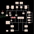
The 8051 has 4 registers bank . The B0, B1, B2, and B3 stand for banks and each bank contains eight general purpose registers ranging from ‘R0’ to ‘R7’. A register is a storage element that can be store bits of information, A register file is a collection of registers, which are the same length. A register bank is a collection of registers, which are the same length. what are the difference between registers , registers file and register bank. what are the use of registers bank in 8051?
 

MrChips

Joined Oct 2, 2009
30,806
The concept of register banks and files does not apply to all computer designs. It is specific to particular computer architectures, as in Microchip PIC and Intel MCS-51.
A register is a storage element that can be store bits of information.
Correct. In most architectures, a register is a hardware element in the CPU. There could be more than one register for different functions.
A register file is a collection of registers
Correct also. When you have a collection of such registers, you may call the single collection a "register file", especially if you can access a specific register using a binary address. For example, you might have 8 registers and each register might have a 3-bit address that would be part of the machine instruction code (as in the case of Microchip PIC).
A register bank is a collection of registers
Correct, but usually in memory. On the MCS-51, special purpose registers are not hardware elements but are actually in memory space. There are 32 bytes from address 0000-0001F that are reserved for four banks of 8 registers. Which bank of registers are to be used as special purpose registers depends on which bank is selected. This is used in "context switching", i.e. your program can switch from one context to another, using the same register names, R0 - R7, and not conflict with register usage in a previous context.
 

Papabravo

Joined Feb 24, 2006
21,225
A bank of registers is useful in handling interrupts. Instead of saving R0 thru R7 on the stack you just switch the register bank pointer(selector) and you have effectively saved the registers in use at the time of the "call" to the interrupt service routine. Since the register bank pointer (selector) is in the PSW which is saved on the stack it will be restored when the interrupt service routine executes a RETI (Return from Interrupt ) instruction.
 

MrChips

Joined Oct 2, 2009
30,806
A bank of registers is useful in handling interrupts. Instead of saving R0 thru R7 on the stack you just switch the register bank pointer(selector) and you have effectively saved the registers in use at the time of the "call" to the interrupt service routine. Since the register bank pointer (selector) is in the PSW which is saved on the stack it will be restored when the interrupt service routine executes a RETI (Return from Interrupt ) instruction.
Yes. The RCA COSMAC 1802 was one of the first microcontrollers on the market (1976) and it employed context switching. It has popular in the satellite industry because of the CMOS technology, low power, and radiation hardness.
 

Thread Starter

Parth786

Joined Jun 19, 2017
642
We can transfer data from one register to another register but Why data transfer between general purpose registers to general purpose registers is not possible in 8051. Example Mov R0, R1?

These are 32 general purpose registers address from 0 h to 1 h.
Address range of Register Bank 0 ( 00 h to 07 h)
Address range of Register Bank 1 ( 08 h to F h)
Address range of Register Bank 2 ( 10 h to 17 h)
Address range of Register Bank 3 ( 18 h to 1F h)

Address of register R0 (Hex value = 00 h)
Address of register R1 ( Hex value = 01 h)
Address of register R2 (Hex value =02 h)
Address of register R3 (Hex value =03 h)
Address of register R4 (Hex value =04 h)
Address of register R5 (Hex value =05 h)
Address of register R6 ( Hex value =06h)
Address of register R7 ( Hex value =07 h)
Address of register R0 (Hex value = 08 h)
Address of register R1 ( Hex value = 09 h)
Address of register R2 (Hex value = A h)
Address of register R3 (Hex value = B h)
Address of register R4 (Hex value = C h)
Address of register R5 (Hex value = D h)
Address of register R6 ( Hex value = Eh)
Address of register R7 ( Hex value = F h)
Address of register R0 (Hex value = 10 h)
Address of register R1 ( Hex value = 11 h)
Address of register R2 (Hex value = 12 h)
Address of register R3 (Hex value = 13 h)
Address of register R4 (Hex value = 14 h)
Address of register R5 (Hex value = 15 h)
Address of register R6 ( Hex value = 16 h)
Address of register R0 ( Hex value = 17 h)
Address of register R0 (Hex value = 18 h)
Address of register R1 ( Hex value = 19 h)
Address of register R2 (Hex value = 1A h)
Address of register R3 (Hex value = 1B h)
Address of register R4 (Hex value = 1C h)
Address of register R5 (Hex value = 1Dh)
Address of register R6 ( Hex value = 1E h)
Address of register R0 ( Hex value = 1F h)
 

Thread Starter

Parth786

Joined Jun 19, 2017
642
The CPU can access data in various ways. The data could be in a register, or in memory, or be provided as an immediate value. These various ways of accessing data are called addressing modes. The various addressing modes of a microprocessor are determined when it is designed, and therefore cannot be changed by the programmer.

The 8051 has five addressing modes
1) Immediate addressing modes.
2) Register addressing modes.
3) Direct addressing modes.
4) Register indirect - addressing mode.
5) Indexed addressing mode.

1) Immediate addressing modes.
MOV A, # data ; transfers an 8-bit data immediately to the accumulator
In general we can write MOV A, #data. it transfers an 8-bit data immediately to the accumulator (destination operand). The ‘#’ symbol before data indicates that operand is a data (8 bit).

what is encoding
Code:
MOV A, # data
Example MOV A, #0FFh
Byte 2
Cycle 1
Encoding  01110100 data
---------------------------------------------
C --AC--F0--RS1--RS0--OV--  --P
------------------------------------------------
 

shteii01

Joined Feb 19, 2010
4,644
The CPU can access data in various ways. The data could be in a register, or in memory, or be provided as an immediate value. These various ways of accessing data are called addressing modes. The various addressing modes of a microprocessor are determined when it is designed, and therefore cannot be changed by the programmer.

The 8051 has five addressing modes
1) Immediate addressing modes.
2) Register addressing modes.
3) Direct addressing modes.
4) Register indirect - addressing mode.
5) Indexed addressing mode.

1) Immediate addressing modes.
MOV A, # data ; transfers an 8-bit data immediately to the accumulator
In general we can write MOV A, #data. it transfers an 8-bit data immediately to the accumulator (destination operand). The ‘#’ symbol before data indicates that operand is a data (8 bit).

what is encoding
Code:
MOV A, # data
Example MOV A, #0FFh
Byte 2
Cycle 1
Encoding  01110100 data
---------------------------------------------
C --AC--F0--RS1--RS0--OV--  --P
------------------------------------------------
WTF?
 

MrChips

Joined Oct 2, 2009
30,806
The CPU can access data in various ways. The data could be in a register, or in memory, or be provided as an immediate value. These various ways of accessing data are called addressing modes. The various addressing modes of a microprocessor are determined when it is designed, and therefore cannot be changed by the programmer.

The 8051 has five addressing modes
1) Immediate addressing modes.
2) Register addressing modes.
3) Direct addressing modes.
4) Register indirect - addressing mode.
5) Indexed addressing mode.

1) Immediate addressing modes.
MOV A, # data ; transfers an 8-bit data immediately to the accumulator
In general we can write MOV A, #data. it transfers an 8-bit data immediately to the accumulator (destination operand). The ‘#’ symbol before data indicates that operand is a data (8 bit).

what is encoding
Code:
MOV A, # data
Example MOV A, #0FFh
Byte 2
Cycle 1
Encoding  01110100 data
---------------------------------------------
C --AC--F0--RS1--RS0--OV--  --P
------------------------------------------------
It is saying that the instruction for MOV A, #data is two bytes long.
The first byte is $74.
The second byte is data.
 

Thread Starter

Parth786

Joined Jun 19, 2017
642
Accumulator in 8051

My basic understanding, register is integrated circuit that store binary data and register's have some common pins such as data input pins, address pins, data output pins, Enable/ disable pin, Read / write pin, Clock pin ..

accumulator is a register in 8051 which store 8 bit data and by default it receives the result of all arithmetic operation.
accumulator pins (8 bit register)
8 bit data inputs
8 bit address input
8 bit data output
clock input
enable input
how many other pins it have ?

I am trying to find out how many input and output pins in accumulator register (8051). I have searched and can't find anything regarding this topic. even I have been seen datasheet I have gone throw this site https://en.wikibooks.org/wiki/Embedded_Systems/8051_Microcontroller there is diagram. I have edited that diagram in paint. If you look at attached diagram , there is accumulator. I have mention in red and green color for input and output pins . I don’t find any clue that how many pins accumulator have, Is it possible to find out how many pins in accumulator register?
 

Attachments

Papabravo

Joined Feb 24, 2006
21,225
The ACC is one of the Special Function Registers; it is mapped into the SFR memory space at address 0xE0. It has 8 inputs and 8 outputs, but they are not connected to any actual "pins". The connections are internal to the chip. Some other registers mapped into the SFR memory space are as follows:
  • PSW register at address 0xD0
  • B register at address 0xF0
  • SCON register at address 0x98
  • DPL register at address 0x82
  • DPH register at address 0x83
  • P0 register at address 0x80
  • P1 register at address 0x90
 
Last edited:

Thread Starter

Parth786

Joined Jun 19, 2017
642
The ACC is one of the Special Function Registers; it is mapped into the FSR memory space at address 0xE0. It has 8 inputs and 8 outputs, but they are not connected to an actual "pins". The connections are internal to the chip.
I know they are not connected to actual pins of 8051 Microcontroller. you are saying "The connections are internal to the chip" so lets discuss on internal connection. I agree ACC register is not connected to actual pins of 8051 but lets assume it have some wires, some wires for inputs connection and some wire for output connections.


8 wires for input data connections
8 wires for output data connection
8 wires for address connection
1 wire for read/write connection
1 wire for enable/ disable connection
1 wire for clock connection

1. Does it make any sense ?
2. do you agree that it should have minimum 27 wires ?
3. if not than how we will verify that how many wires it have ?
4. what is way to find out internal connection of registers in 8051?
 
Last edited:

MrChips

Joined Oct 2, 2009
30,806
I know they are not connected to actual pins of 8051 Microcontroller. you are saying "The connections are internal to the chip" so lets discuss on internal connection. I agree ACC register is not connected to actual pins of 8051 but lets assume it have some wires, some wires for inputs connection and some wire for output connections.


8 wires for input data connections
8 wires for output data connection
8 wires for address connection
1 wire for read/write connection
1 wire for enable/ disable connection
1 wire for clock connection

1. Does it make any sense ?
2. do you agree that it should have minimum 27 wires ?
3. if not than how we will verify that how many wires it have ?
4. what is way to find out internal connection of registers in 8051?
Data lines could be combined into 8 input/output line (we don't know).
Why does it need address wires?
Why does it need enable /disable?

Why do you need to know all of this?
 

Papabravo

Joined Feb 24, 2006
21,225
I know they are not connected to actual pins of 8051 Microcontroller. you are saying "The connections are internal to the chip" so lets discuss on internal connection. I agree ACC register is not connected to actual pins of 8051 but lets assume it have some wires, some wires for inputs connection and some wire for output connections.


8 wires for input data connections
8 wires for output data connection
8 wires for address connection
1 wire for read/write connection
1 wire for enable/ disable connection
1 wire for clock connection

1. Does it make any sense ?
2. do you agree that it should have minimum 27 wires ?
3. if not than how we will verify that how many wires it have ?
4. what is way to find out internal connection of registers in 8051?
No that is not how I would approach the internal design of an 8051. In fact I have worked with a Verilog model, and as has been pointed out things don't necessarily work the way you think they do. There are many Verilog(VHDL) models in the public domain and this would be a great way for you to gather the requisite information. Unfortunately the original design has not been released into the public domain so we really can't answer your question with any precision.
 

Thread Starter

Parth786

Joined Jun 19, 2017
642
Unfortunately the original design has not been released into the public domain so we really can't answer your question with any precision.
Should I give up ? I am trying to implement basic rule " If you know the basic than you can understand complex things". I understand basics of register but I having trouble to understand other type of registers

Why do you need to know all of this?
Because I don’t know the internal connection of register in 8051. Looking only block diagram, I am not able to understand what’s are happening inside microcontroller. I want to understand internal connection of wires within microcontroller.

Register is device that is used to store binary data.
A register has two inputs, a data input and a clock input.

8 bit Register with 17 wires
· 8 bit data inputs
· 8 bit data outputs
· Clock input

The clock input is typically called the "enable". When the enable signal is high, the register stores the data input. When the clock signal is low, the register value stays the same

Examples
Input wires --à bit Register------à output wires
Wire1, wire2, wire3 wire4 ---àRegister-------à Wire1, wire2, wire3 wire4

If you look at both examples second example is more useful than first because there is much information. We can see the use of each wires.

Registers are the most common component of 8051 Microcontroller. I am studying registers of 8051 microcontroller. 8051 contain many of registers like A register, B register, RAM Address register, Program address register, temp1, Register, Temp2 Register .. and so many registers are built on single chip.

so If I have basic register now I want to make it as accumulator register.
How to make it as accumulator register? What extra function we need to add to make it as accumulator

· 8 bit data inputs (eight wires)
· 8 bit data outputs (eight wires)
· Clock input

If I get the idea than I will try to add more registers
 

Papabravo

Joined Feb 24, 2006
21,225
You are vastly overthinking all of this. The block diagram is the appropriate level of detail, and you can use it in conjunction with each instruction in the instruction set to follow the data from place to place within the processor. Take the MOV instruction with the ACC as the destination and an immediate operand from the instruction register.
 

hexreader

Joined Apr 16, 2011
581
Parth786 is Vead?

The posts look very familiar compared to Vead's posts from many years ago, but hard to believe the two people are really the same person.

I am confused (but nothing new there :) }
 

Thread Starter

Parth786

Joined Jun 19, 2017
642
@vead, did you finish reading Understanding Small Microcontrollers like I asked you to do?
Why did you mention this name @vead. I haven’t finished my course. I am doing embedded system course from CDAC. I have subject 8051 and embedder system. I am taking class since one and half months. I have book mazidi http://www.iust.ac.ir/files/ee/pages/az/mazidi.pdf
look at book there is page number 30. Chapter inside CPU. Every time I hear only one name register during the class.

I asked my professor about internal connection in 8051. They didn’t tell me much they said ,do study search on internet, there is lot of information blaaaa bla every dialogs. I have been searching since last three to four days. I couldn’t find much information. Everything is going over on my head because I don’t understand what happening inside. Now I am thinking how do people say smoothly go and search on internet but they don’t think the level of student. why they don't teach with real time example
 
Top