Gate Driver Supply

Thread Starter

Joester0064

Joined Jun 14, 2023
77
Hi All,

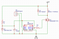
I am wondering if this is a sufficient way to provide power to Vdd for this gate drive IC. Just using a Zener diode and cap for transient response support for the gate drive.

1721760808947.png
 

Irving

Joined Jan 30, 2016
5,019
2N7002 doesn't need much gate drive. What's the spec on your 1H inductor as that will determine how much gate drive is needed.
 

Ian0

Joined Aug 7, 2020
13,100
Series resistance of the inductor is important. Otherwise the current will keep increasing for ever (or until the 2N7000 vapourises)
 

Irving

Joined Jan 30, 2016
5,019
What MOSFET? But spec of inductor is critical as is your expected frequency of switching. Without that info,can't advise.
 

Thread Starter

Joester0064

Joined Jun 14, 2023
77
Thanks all for the input, here is an updated schematic with the correct part numbers for the gate driver and fet along with the inductance and internal resistance. I am mostly concerned with the 15Vzener and cap being able to properly supply the gate drive.
1721910332918.png
 

Attachments

ronsimpson

Joined Oct 7, 2019
4,652
What speed is the PWM. The diode 1N4007 is very slow 2uS. Look at the UF4002 50nS. I know it is not in production now but look for something like it. You only need 100V diode not 1000V.
 

Ian0

Joined Aug 7, 2020
13,100
The current required for the driver is approximately equal to the driver’s quiescent current, plus the product of the MOSFET’s gate charge and the switching frequency.
if that current is less than the current through your 1k resistor, you are OK, but don’t forget that the zener has to pass the rest of the current and will dissipate some power.
 

ronsimpson

Joined Oct 7, 2019
4,652
Put a 0.1uF ceramic capacitor across pins 5-8 on U2. C1 is not good for high current.
I often use a 0.01uF at the IC, A 1 to 10uF ceramic close and an ele cap anywhere.
 

schmitt trigger

Joined Jul 12, 2010
2,036
The current required for the driver is approximately equal to the driver’s quiescent current, plus the product of the MOSFET’s gate charge and the switching frequency.
Exactly this. That’s why I bolded the statement.
With high gate charge Mosfets, like high voltage devices, and high switching frequencies, I have measured currents close to 100 mA.
 

Irving

Joined Jan 30, 2016
5,019
In terms of spec, it's about the furthest you can possibly get from the 2N7002!
Its an awful device. 450mOhm Rds(on), 5A Id continuous, and, oddly for a TO-247 package, a 1.8°C/W junction to case thermal resistance (most are around 0.2°C/W).

I can't make their SPICE model work.
 

Attachments

Thread Starter

Joester0064

Joined Jun 14, 2023
77
Put a 0.1uF ceramic capacitor across pins 5-8 on U2. C1 is not good for high current.
I often use a 0.01uF at the IC, A 1 to 10uF ceramic close and an ele cap anywhere.
highest switching speed will be 500Hz, and pulse width about 10%, what does the cap between 5 and 8 do? maybe a 1000uF for C1?
 

BobTPH

Joined Jun 5, 2013
11,469
highest switching speed will be 500Hz, and pulse width about 10%, what does the cap between 5 and 8 do? maybe a 1000uF for C1?
Then you probably don’t need a gate driver if you pick an appropriate MOSFET.

What is the voltage and current capability of the PWM input?
 
Top