How this circuit works, gate drive used instead of timer chips
K Thread Starter karas Joined Sep 8, 2011 216 Nov 24, 2025 #1 How this circuit works, gate drive used instead of timer chips Attachments IMG_0285.jpeg 5.3 MB Views: 25
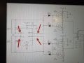
MrChips Joined Oct 2, 2009 34,982 Nov 24, 2025 #2 Look up EL7212 datasheet. It is a dual high current inverter driver wired as an astable circuit, i.e. it is an oscillator.
Look up EL7212 datasheet. It is a dual high current inverter driver wired as an astable circuit, i.e. it is an oscillator.
K Thread Starter karas Joined Sep 8, 2011 216 Nov 25, 2025 #4 Attachments gate_drive _ps.asc 3 KB Views: 1
K Thread Starter karas Joined Sep 8, 2011 216 Nov 25, 2025 #5 Please can you check why the simulation is not working
K Thread Starter karas Joined Sep 8, 2011 216 Nov 25, 2025 #7 MrChips said: Why do you need two EL7212C ? Click to expand... The spice model has only one output that is why I use two
MrChips said: Why do you need two EL7212C ? Click to expand... The spice model has only one output that is why I use two
ericgibbs Joined Jan 29, 2010 21,509 Nov 25, 2025 #8 hi karas, Check this simulation. My EL model layout is different. E Attachments gate_drive _psX1.asc 2.6 KB Views: 1 el7212c.asy 734 bytes Views: 1
 Facebook
 Google
 GitHub
 Linkedin
 5.3 MB Views: 25


