Garage Door Safety Sensor Used Independent

Thread Starter

circle

Joined Nov 13, 2017
7

Thread Starter

circle

Joined Nov 13, 2017
7
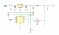
I found this circuit from the internet and not sure this can give the result
Can someone please give me an expert opinion
Thanks
circuit.png
 

MisterBill2

Joined Jan 23, 2018
28,000
Thanks Ylli,
It's hard to figure out the problem without the schematics
As I mentioned earlier, it's working when connected to the garage door opener
Why it's not working when connected to an external power source?
It may be that a circuit of the garage door opener is available. Those beam-break safety switches are actually complex circuits.So in the sensor is a bit of electronics, which is why it does not work as you wish.
 
I have an old Genie Garage door safety sensor and like to use Independent without connecting to the actual Garage Door.
It's working perfect when it's connected to the Garage door opener

I tried to connect to the 12V DC power supply and it shows both green and red LEDs
When both in line, it doesn't stop blinking the RED LED
Is it possible make this work?
What's the actual power supply required this to work?
Thanks in advance
Your problem is complicated. I only know that The output voltage for the garage door sensors should be between 5-6 volts DC. You can Disable Garage Door Sensors and stress free. I give you easy steps like cut off the power > remove the sensor > go for new sensor.
 

MisterBill2

Joined Jan 23, 2018
28,000
Here is an idea, which would allow you to know how it normally functions, but it would only work if you have the original door opener control unit that the sensors connected to. the plan is to re-connect the sensors to the unit and then measure the voltage across each one while the beam is unbroken , and the when the beam is broken. That will tell you which one is the source and which one is the sensor. Then, measure the current drawn by the sensor with both the beam unbroken and then with the beam broken. That will allow you to know the source resistance for the sensor. The final step is to measure the voltage across the sensor connections with the sensor disconnected. That will tell the sensor supply voltage. At that point you would have all the information needed to use them as a security system sensor set.
 

Tonyr1084

Joined Sep 24, 2015
9,744
Just so happens I have a Genie GDO (Garage Door Opener). Back a while ago I had a problem with the opener. Turned out to be the main board had developed a problem. Genie sent me a new board and the right wall switch for the new board.

The old operated on 5 volts. There was a constant power through a resistor. Don't know off hand what those values were, so bear with me and the lack of information, but when you pushed the close button (same as the open button, there was just the one button) the 5 volts would be pulled low, based on some pulse train frequency that the mother board would interpret it as a command to close (or open) the door. The wall switch had two other buttons as well, and they would force a different pulse string in a similar manor. Depending on which button was pressed, the GDO would respond accordingly.

Now, my safety beam sensors have two wires each. Either wire can be connected to either terminal. Not sure how they figured that part out, but regardless of how you wired it - you couldn't wire it wrong. Now, concerning the beam and sensor, for the sake of argument, lets call one wire positive and the other negative, each sensor has the same wires. At the GDO you twist two wires together. Again, for the sake of argument, lets just say the two positive wires were twisted together, and pushed into the GDO Safety Beam connector. Take the other two (negative) wires, twist them together and shove them into the other GDO Safety Beam connector. Exactly how they work - I don't know. I DO know they don't work like an ordinary switch. Most infra-red beams operate by sending a signal from a transmitter to a receiver. The receiver detects the beam and activates a relay (or vice versa). When the beam is broken the relay falls out and the NC contacts close, making the circuit.

Not so with the Safety Beam sensors. They're always connected and always sending a pulse train back to the GDO. When the beam is blocked the pulse train changes (I'm guessing) causing the GDO to think something is in the way, and reverse the door to the full open position. I don't think you're going to find a good application for using your safety beams for something else. I'm sure you can, but you'll need a micro processor and some programming to detect the changes when the beam is solid and when it is broken. But it's that pulse train thing that prevents you from bypassing the safety beam functionality. You can't short the leads, you can't leave them open. You can't even introduce a variable resistance and adjust till the door works.

Well, I hope you find a use for them. I'd be interested to hear if you solve the problem. Maybe it might start a new train of projects.
 

MisterBill2

Joined Jan 23, 2018
28,000
WOW!! Thanks Tony! I had not ever done anything with this type of sensors aside from aligning them , and so i had presumed that they were at least a bit like the industrial ones. Wrong assumption. The fact that they can function correctly when tied in parallel is very interesting. Still, it is most likely that one contains the emitter and the other contains the detector. Now if I can assume that there is a fail-safe functionality included so that if any wire breaks the door does not close automatic, but requires the button to be held to keep it moving, then it may be that in the clear mode, beam not obstructed, the pair draws more current, and with the beam broken less current is drawn. To verify this one would connect them as described, with a current meter in series, and provide a DC voltage. With the two devices facing so the beam is unbroken, some current would flow, and it should become less if the beam is broken. That would make sense, and be simple to use the resulting change in current. That possibility would be simple to check and see if it works that way.
If it works some other way, I know how the radio shack photo alarm system works and I can describe it in the future.
 

Tonyr1084

Joined Sep 24, 2015
9,744
@MisterBill2 If I were at home I could pull up some screen shots I took of trace patterns from my GDO switch. It's likely the Safe-T-Beam (STB) sensor works similar. I don't think it has to do with current because I experimented with dead shorting the two wires, obviously leaving them open did nothing, and varying them from near dead short to very high resistance did nothing to actuate the door. Or reverse the door. In short, if the GDO (Genie) is not seeing a specific frequency it's not going to close the door.

True, you can force a door closure by holding the button down, most, if not all are like that. But the Genie, without the STB they won't close unless you hold the button. Also on my home computer (on the laptop on a job site) I have a schematic for using a timer to actuate the door if it's open at certain hours. The thought is that if the door is open at - lets say, 7:00 AM, after wife has gone to work, and the door is open, the door will automatically close. Because of the way you force a closure by holding the button I had to come up with a way to actuate the door then disconnect and lock out the command for one minute. If something blocked the STB the door would open and not try to close again until the next pre-set hour. Otherwise if I didn't lock out an accidental continuous command I could crush someone or something with the door.

I used a programmable timer that can be set to any time to switch on and be on for any length of time from one minute to much much longer. Using the one minute function I can have the door close up to 20 different times during the day or night. Suppose I go to bed with the door open. At a given hour it will close if open. If it's closed it can not open because to actuate the door switch the door has to be in the open position and actuate two microswitches. As the door closes it's important that the first switch opens before the second, so that the lockout can happen. I've posted that drawing somewhere on someone else's thread, I'll see if I can spot it. If so, I'll link to it. Just for fun.
 

MisterBill2

Joined Jan 23, 2018
28,000
OK, Tony. You have actually seen and touched the hardware and put real instrumentation on the wires, while I once saw a system and adjusted the beam alignment. So my guess was a lot off. Your implementation of the automated closing scheme is a good example of great engineering, thanks for sharing it.
So now the question would be how to utilize the safety devices as a beam-break security system, with the goal being to do it without modifying them. That is a challenge indeed. My observation of scrapped GDO packages is that there is one custom IC that does everything , which allows for some interesting external I/O patents to keep others away. So now if the safety beam system does not use a variation in current or voltage then it must be either pulse frequency or duty cycle that gets changed. Those are a bit more complex to sense in a non-microprocessor/ non-microcontroler arrangement. But that would be the better choice. If it is a change in frequency then the LM2917 applications already show a frequency sensing switch circuit, while a change in duty cycle would require a one-shot missing a retrigger time, I think.
 

Tonyr1084

Joined Sep 24, 2015
9,744
It was @AlbertHall who helped me with my GDO back a year or two ago. He helped me understand how they were using the 5 volt line not only as power to the door switch but also how it was being used to ring back the frequency the GDO was reading. So I'm assuming that the STB's (Saf-T-Beam) is operating on a similar principal, ringing the 5 volt line somehow. 1) I'm not at home to test how the STB's work. 2) I don't have a reason for investigating how to go about turning STB's into an IR Trap to detect when the beam is broken.

If I were to go at it - I'd set up two of them powered through a voltage divider of some sort so that I'm not dragging 5 volts all the way to ground. Then, with the beams face to face I'd read their signal on a scope. Then block the beam and see how their signal changes. Or stops. Then I would have to figure out how to detect that particular frequency and make it do some sort of work, like triggering a relay or something. Since I don't have access to my test bench the best I can do right now is theorize on how they work. The right way to understand how they work is to actually bench test them and record my results. Once I know how they operate I can develop a plan. The GDO closing system I designed I did so because a couple times we've gone to work leaving the door open. And there have been times we went to bed, again, with the door open. Fortunately we live in a pretty safe neighborhood; but still, why tempt people to explore and maybe re-own some of my stuff? So I thought about getting one of those GDO's that have an ap on my phone that I can close the door from anywhere in the world. But they're way too expensive. The timer, relays and switches were so cheap that I decided to just go with much of what I already had. I only had to buy the programmable timer.

But I'll give it some thought. I DO have a nuisance cat that comes around causing trouble, so maybe a beam could detect his presence and trigger an air valve solenoid just to scare the fur off of him and make him nervous about coming around. Already set up a snap trap, but once he got snapped with a charged capacitor he learned to stay away from the trap but still venture into my yard. I've even thought about putting down fly paper. But one thing I don't want to do is harm an animal. Just because it has a bad owner - there's no good reason to punish the animal. The snap trap was to encourage him to stay away. Fly paper would be along the same line, as would an air blast to suddenly hiss at him and make him poop his teeth as he runs for his life.

But I also think that infra-red beams are widely available and cheap. And much easier to set up. Back when I installed burglar alarms, the IR beams were set up so that they triggered a double throw relay so that you could set it up as make to break, break to make or break to break and set off the alarm. Anyway, I need my beauty sleep. A LOT of it.
 

MisterBill2

Joined Jan 23, 2018
28,000
Compressed air driving water can be very startling to a cat and yet not lethal to anyone or anything.Rats and mice don't like it either. And a cheap laser is easier to align because of being able to see the beam. Your description of the analysis process is about what I was thinking about, except that you put in all of the details. Now for remotely closing the door, a DTMF decoder module connected to a fax machine phone line will allow control without anybody having a clue that it exists, no matter how hard they examine the phone. And the module costs less than $4 and comes complete with no documentation at all. But the binary decoding logic is rather simple, and hardware logic is as reliable as can be.
 

bendrjr

Joined Nov 13, 2018
1
I have been looking to use these sensors to detect people crossing through. My garage door sensor has a 12 volt supply, but it has only two wires (in parallel) going between the motor unit, transmitter and receiver. So the detection and power is combined in these two wires. I put a resistor across the wires and found that 150 ohms to ground drops the voltage to 6 volts, meaning there is a 150 ohm pull-up in the motor unit from 12 volts and the positive wire to the sensor boxes. So make sure when you power the sensors that there is a resistor in the positive wires.
I bought some used sensors on-line for $16 and looked inside. It is a clever scheme: The IR transmitter (TX) has a pulse generator that sends short pulses of IR at around 330 hz. The receiver detects the pulses and a transistor pulls the supply line down to about 2 volts during the brief period of the pulse. Large capacitors in the TX and RX keep the circuits alive during the period. Both TX and RX have diode bridges so its no problem if their supplies are reversed. A pulse detector in the motor unit senses the pulses and won't let the door close when no pulses are present.
Clever circuit. It's pretty foolproof for connecting in your garage, yet hard to defeat its purpose for the average person, since you can't do this by shorting or opening any of the wires.
I will see if I can design a pulse detector to sense when they are present or not. Stay tuned.
 

MisterBill2

Joined Jan 23, 2018
28,000
A series transformer in the power lead to the two blocks could provide a string of voltage pulses from the secondary to charge a capacitor through a diode. Then a simple transistor switch could drop out a relay when the pulses stopped. Of course there are other ways to do it but a small cheap transformer is simple and provides isolation and does not require an arduino board and programming. The transistor could be an MPSA13, a very high gain device that can very easily drive such a relay.Less than $5 for parts and it is working. That would be one choice.
 

Tonyr1084

Joined Sep 24, 2015
9,744
I agree. The TS posted 7 messages, all of which are in this thread. There has been no other activity from the TS for a year now, so, yes, looks like he's gone.
 

MisterBill2

Joined Jan 23, 2018
28,000
For whatever reason this thread popped up when I was looking for new threads to visit. And being as it was sort of early in the day I neglected to check the date. Perhaps there is some way tomake it clearer that threads are old? How about changing the background color? That would be a webmaster thing though.
 

Tonyr1084

Joined Sep 24, 2015
9,744
I've done it too. After responding to a thread I noticed down below the reply pane there were more questions similar to the one I just responded to. Clicked on one of those without realizing how old it was. Responded to that and promptly got scolded by someone for reviving an old thread.

I've since discovered that there IS a warning box that appears when you're responding to a thread over one year old since the last posting. Maybe that should be changed to six or nine months. A warning that says "THIS THREAD HAS BEEN INACTIVE FOR X MONTHS. THE ORIGINAL POSTER OF THIS THREAD HAS LIKELY GOTTEN THE ANSWER THEY WERE LOOKING FOR. DO YOU WISH TO CONTINUE?"
 
Top