Gain of op-amp amplifier with potentiometer

Thread Starter

ham3388

Joined Jul 3, 2012
97
Hi dears
Below is a worked example with solution from the university material plus an assignment asking for solution. I did solved it but I am not sure about my solution. Could you please go through it and give some kind of help and support to understand it or give some means to solve it if it is incorrectly been solved.
 

Attachments

bertus

Joined Apr 5, 2008
22,989
Hello,

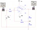
@shteii01 , you forgot to take the 100 K resistor (R3 in the schematic) between the output of the opamp and the 1 K resistor to ground into account.

Bertus
 

DGElder

Joined Apr 3, 2016
351
Ham, I think you may be confused about how a potentiometer works- Rp is not R3: Look up potentiometers in Wiki.

It is the same circuit as the example with variations only in R3 and R4 and you are given the gain formula in the example. All you have to do is figure out R3 and R4 which depend on the pot wiper position, "x", and then plug the numbers back into the gain formula. For example: Part b) R4 = x*10K + 1K = 8k and R3 = (1-x)*10K = 3K.
 
Last edited:

shteii01

Joined Feb 19, 2010
4,644
Ok. I see what I did wrong earlier. The pot resistance does not just go away. It moves as the junction moves. When x=0, the whole resistance of the pot is "above" the junction, or, as bertus said, the 10 kOhm resistor is between output of op amp and the junction of the 100 kOhm and 1 kOhm resistors.


x zero.jpg
 
Last edited:

Thread Starter

ham3388

Joined Jul 3, 2012
97
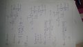
I went through the Wikipedia and other resources and recalculated it based on those resources plus guidance from Mr. DGELer and Mr SHTEII01.
Could you please look on the below attachment and give your comments.
 

Attachments

dannyf

Joined Sep 13, 2015
2,197
Ok. I see what I did wrong earlier.
the inverting end is at round. So current flows from V1 to the inverting end and then R2 and then to Vx. That current is I1 = V1 / R1.

So Vx = - I1 * R2 = - V1 / R1 * R2.

The current flows from ground to Vx through R4: I4 = -Vx / R4.

I1 + I4 flow through Rp to Vout.

Vout = Vx - (I1 + I4) * Rp = Vx - (V1 / R1 - Vx / R4) * Rp = (-V1 / R1 * R2) - (V1 / R1 + V1 / R1 * R2 / R4) * Rp = (V1 / R1) * (-R2 - Rp - R2 * Rp / R4).

In this case, it is 11.1v.

It can be re-expressed to be more intuitive.
 

DGElder

Joined Apr 3, 2016
351
Ham, only in part b) are the R3 and R4 values correct. If x=0 that means the wiper is at the bottom of the resistor (zero distance from the bottom), so the entire 10K is above the wiper. When X=1 the wiper is at the top so that the entire 10K is below the wiper. My formula for R3 and R4 applies for all wiper positions. Post #8 correctly represents the pots contribution for x=0.
 
Last edited:

dannyf

Joined Sep 13, 2015
2,197
another approach would be to think of it from Vout's perspective: Rp and R4 are in parallel. So the feedback resistance is R2 + Rp//R4.
 
another approach would be to think of it from Vout's perspective: Rp and R4 are in parallel. So the feedback resistance is R2 + Rp//R4.
Are you saying that the feedback resistance is R2 + Rp||R4, therefore the gain is -(R2 + Rp||R4)/R1? Is this for the case x = 0? It isn't the same as the correct expression you gave in post #11: (-R2 - Rp - R2 * Rp / R4)/R1
 

DGElder

Joined Apr 3, 2016
351
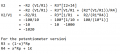
The text's gain derivation was a bit difficult to follow and cookbookish, but I got the same answer, -1020, deriving from basic ideal op amp principles - shown in attached image.

For the potentiometer version I got:
x=0, G = -111
x=0.7, G = -14
x= 1.0, G = -10
 

Attachments

Last edited:

dannyf

Joined Sep 13, 2015
2,197
Think from Vout's perspective. Vout + Rp (serial) can be viewed as a current source of Vout/Rp + Rp (parallel).

Rp in parallel + R4 in parallel -> Rp//R4 in parallel, with a current source of Vout/Rp -> a voltage source of Vout * (Rp//R4) / Rp + Rp//R4 in serial.

The rest is similar to a typical inverting amplifier.

This approach is used to form large feedback resistors.

A good approach for a voltage amplifier. A terrible approach for a transimpedance amplifier.
 
Top