Fundamental comparator problem

Thread Starter

cognas

Joined Feb 24, 2017
58
I wanted to make a zero crossing sensor that would give a pulse every time the mains crossed through zero. I know there are opto-coupler zero-crossing sensors (eg H11AA1, which I have), but there are reasons I don’t want to use one.

I decided to make the following …

ZeroCrossing.PNG

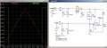
The top section is a 5V PSU.

The idea was that the LM393 comparator develops a square wave, synchronised with the mains, and the second XOR gate makes a pulse by comparing that square wave with a version of itself that is delayed by the RC network on the lower leg. While the XOR inputs are different (during the delay), the output goes high, giving a pulse every time the mains goes through zero. The first XOR is there partly for buffering and partly for convenience, because it was built on stripboard, and the pins lined up.

The circuit containing the transformer secondary and the diode-limited AC on the comparator inputs would be floating without the pot, but with the pot, it can be swung from 0V to 5V. I originally had one leg tied to ground, but the LM393 didn’t like that.

It works OK, but the pulse that comes out of the XOR bounces for a couple of uS. I traced it back to the comparator, which rings on each transition.
zeroCrossScope.png

In case you can’t read the writing on the image,

Top left : Diode-clamped input to comparator. Top right : Apparently clean output of comparator. Bottom right : edge of comparator output expanded. This is a falling edge, but the rising edge looks similar.
I examined the top left waveform meticulously. The rise time is slow, taking about 220uS, but it is clean – no ringing there.

Browsing around for a solution to my problem, I found that a lot of LM393 users have a similar problem. There have been suggestions to put a 10uF and a 10nF across the 5V rails close to the comparator, but I haven’t found that it helps. It’s on a breadboard, which isn’t the ideal environment, but connecting the capacitors doesn’t noticeably improve matters, so I don’t think that putting it on Veroboard will help either. It was originally on Veroboard, but although I have added the pot and unlinked the transformer secondary circuit from ground, the ringing is the same.

Is this an artifact of the LM393? Is there another comparator I should be using? Maybe an op-amp? Any other suggestions?
 

MrChips

Joined Oct 2, 2009
30,808
To add hysteresis to the comparator, place a resistor from pin-1 to pin-3 of the comparator (and pin-7 to pin-5, if that is the section you are using).
Start with 1MΩ. If that doesn't work, try 470kΩ, 330kΩ, 220kΩ, until you get the desire results.
 

Thread Starter

cognas

Joined Feb 24, 2017
58
Thanks Gents, I tried the hysteresis, using a resistor between the output and the +ve input (pins 7-5), but it didn't fix the ringing.
I started with 1.5M, and went down to 560k, 270k,150k, 100k, 56k. Ringing stayed about the same, though the effect of hysteresis on the input waveform is clearly visible.
Hysteresis.png
All waveforms are w.r.t. the PSU ground.

A: Rising edge of output. I couldn't trigger on it properly, but it's clear to see that it is still ringing.
B: The falling edge
C & D show the falling and rising edges of the output displayed with the input waveform. This looks like negative feedback, but note that this waveform is read on pin 6, which is the negative input. The positive input (pin 5) is a square wave with what looks like fast rise/fall times, but when the transitions are expanded, there is ringing on them too. This can be got rid of with a 10nF capacitor from pin 5 to ground, but it also screws up my timing a bit, and even when it is in place, the output is still ringing about the same.

I have a 741 op-amp, and I'm going to give that a go. I think the output will be fast enough for my application, and the datasheet makes it seem very suitable : "The amplifiers offer many features which make their application nearly foolproof " - a fool's dream! ... " overload protection on the input and output, no latch-up when the common-mode range is exceeded, as well as freedom from oscillations." Now we're talking!
I'll let you know.
 

frpr666

Joined Feb 2, 2010
50
Attached is an example of the comparator which fires "1" when the input voltage is below 1V.
I had a look at your schematic, be careful about the max. input voltage range for the comparator.
 

Attachments

Thread Starter

cognas

Joined Feb 24, 2017
58
Thanks, frpr666. I may go back to the 393 for another go, though while experimenting, I tried something very similar to what you posted. The output looks great when you display half a cycle on the screen as shown - the problem comes when you expand that edge and look at it in detail. Problem is that I'm using it to trigger the interrupt of a microcontroller, which counts to 256 by the time the next edge comes along.
10mS / 256 = 39uS, which isn't much.

The 741 gives a clean output, but it takes 20uS to go up and 10uD to come back down. The other problem is that it goes up and down between +2V and +4.6V, so it stays pretty much in the TRUE state of a TTL gate.

Maybe I'll see what happens if I do away with the comparator and simply use the inputs of the XOR gate.
 

crutschow

Joined Mar 14, 2008
34,450
I believe what you think is ringing/oscillation is actually pulse to pulse jitter.
You can tell the difference if you capture just one pulse (single-shot setting on the scope).
If it's jitter you will see one pulse with no ringing.
If it's ringing/oscillation you will see that on the single pulse.

Jitter and ringing are two completely different things.
Jitter is caused by the transition occurring at slightly different levels from pulse to pulse on the input waveform due to noise.

Is a few microseconds of jitter really a problem in your application?
One microsecond only corresponds to about a 2mV change at the zero-crossing for a 5Vpk, 60Hz signal.
 

frpr666

Joined Feb 2, 2010
50
@I'm using it to trigger the interrupt of a microcontroller
See the Atmel application note AVR182 about the zero-cross detector. You can save the external comparator and use the uC controler input directly (it has the Schmitt-trigger and protection diodes built-in). You will need one resistor only.
 

Thread Starter

cognas

Joined Feb 24, 2017
58
crutschow - sorry - I pressed Reply, but it didn't give me a reply field, so I tried again - same result. I've rebooted since then, so maybe that's why it works now. I'll see if I can remove the entries.
In answer to your suggestion - it's definitely ringing.

frpr666- thanks for the pointer. I looked at the application note, and it would be a way to go, but I finally simply accepted the ringing and worked around it with MCU code. Your guess was a good one - I am, in fact, using an AVR controller. They suppress lower-priority interrupts while in an interrupt routine, and the interrupt I'm using (INT0) has the highest priority, so I simply keep it in the interrupt routine for longer than it takes for the ringing to die down. It appears to be working.

Thanks to all for your time.
 
If timing is critical its possible that the zero crossing point of the ac voltage on the secondary of the transformer doesn't correspond exactly to the zero crossing point of the mains ac because of the phase change caused by the inductance of the transformer. I don't know if that will actually happen in real life, but it's something to check for
 

Thread Starter

cognas

Joined Feb 24, 2017
58
FierceGuineaPig - thanks very much. That is something I knew, but had completely overlooked.
I'm past the phase of looking at pulses on the scope now, having connected the triac and looking at a light bulb coming on - and it's not working as I had intended - and this just could explain it. I'll check that out. Tech college is a long way behind me now (I'm retired), but as I remember it, the magnetic flux is 90 degrees out of phase with mains input, and the secondary output is 90 degrees out of phase with that. I'll check it out
 

crutschow

Joined Mar 14, 2008
34,450
as I remember it, the magnetic flux is 90 degrees out of phase with mains input, and the secondary output is 90 degrees out of phase with that.
True.
But that means the secondary voltage is essentially in phase with the primary voltage.
I doubt that any small phase shift between the primary and secondary is a factor in what you are seeing.
 

Thread Starter

cognas

Joined Feb 24, 2017
58
crutschow, Yes, it's OK. The transformer wasn't an issue. The unit is working. It's a soft-start for a motor, and when I tested it, I found that after the speed-up phase, when it went into the running phase, it was triggering too soon in the cycle. My running phase became a stopping phase, but it was really easy to correct. A slight out-of-phase problem may have exacerbated matters, but it didn't hold me up long. I thought it would be good to bring it up to speed in one second, but now I think that's too fast, so I'll slow it down in the code. Anyway, the project is so close to working that I won't be needing more help with it, so once again, thanks to all who offered assistance.
 
Top