I don't like it. I don't understand all the details but it bothers me that when Vin is positive, none of the diodes show a positive voltage but they do show positive currents. I wouldn't set it up that way but like I said, I haven't studied it in detail.
Yeah something does not look right. For example IT1 shows there is no current until after a short delay, but then that device stays 'on' for the remainder of the entire cycle. That seems impossible because the device can not conduct in reverse.
BTW, this looks like a controlled bridge rectifier where the devices are SCR's not diodes.
Some clarification might help here too.
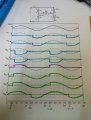
This is a thyristor controlled bridge rectifier. This circuit can be a full-wave rectifier but only when the thyristors are correctly controlled. The graph of Vout shows that only the positive input half-cycles are being fed to the load. So as drawn, it is running as half-wave rectifier.
A thyristor blocks in the reverse direction just like a diode but only conducts in the forward direction after it has received a gate pulse to switch it on. It then stays switched on until the forward current reduces to zero (or below the "holding current") when the voltage reverses.
The graphs show the effect of the thyristors switching on about 45 degrees into the half-cycle.
This circuit is normally used as a full-wave bridge rectifier that can control the power in the DC load R.
It may appear as a thyristor switching half-wave rectifier, but I'm not 100 percent certain the diodes are thyristors as drawn.
The colored lines, illustrating the Vt of each diode has the sine wave (dashed line) there to improve the students artistic representation.
The TS has already identified it was a bridge rectifier. If it were a controlled rectifier, there would have been a control signal on the diagram the student was suppose to fill in. The TS can confirm or deny your suspicions.
The "R" is your load. The turn-on times are α and 180°+α. Depending on α, it could be a full-wave rectifier or not. I would say with α=45°, as the plots show, it is NOT a full-wave rectifier.
Here are the waveforms for the first SCR/Diode if the device labeled "2" was also turned on at the same time or turned on and left turned on.
Note the voltage is the voltage across that first device, and the current is the current through that device.
The device is turned on only once and then is allowed to turn off.
The load is resistive.
The control signal to the gate is shown on the bottom.
The waves are shown as if the devices were SCR's and the input voltage was fairly high like at least 100v peak, but we could still use this diagram if we considered the input voltage to be very low and we dont pay any attention to the control signal as the turn on time is determined completely by the voltage across the device then, and also the voltage drop would be more apparent from that diagram.
A couple other things to note are:
1. The current through the device is zero when it is not turned on.
2. Once it is turned on, it stays on even when the control signal goes away.
3. It turns off when the current wave goes through zero. This is simultaneous with the voltage wave going though zero when the load is resistive but could be different for reactive loads.
 Facebook
 Google
 GitHub
 Linkedin

")


