Full wave bridge rectifier problem

Thread Starter

ilginsarican

Joined Jul 13, 2017
142
Hello,
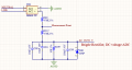
I have two relays to drive two different loads, AC input voltage is 115V RMS, 60Hz, single phase.
There are full wave rectifier circuits after out contacts of relays, respectively.
I use pn: MB6S-TP diode to full wave rectifier and my schematic is attached.

The problem is when one of the relays is on, I measure "Measurement Point" and I see not fully rectified voltage(IMG-8396, purple line on oscilloscope)
I measure fully rectified voltage on "AC_OUT2_V", approximately 1,42V(yellow line on oscilloscope).
Then when both relays are on, I measure voltage similar to IMG-8396 but peak voltage drops and I measure 1,33V on "AC_OUT2_V".
The output of full wave rectifier should be DC but, it isn't.
I will be glad if you share your comments.
Thanks,
 

Attachments

BobTPH

Joined Jun 5, 2013
8,804
You are not measuring the output of the bridge rectifier. You are measuring in the middle of a circuit connected to it. Move the probe up above the 470 K resistor if you want to measure that.

And it will still not be DC.

Bob
 

ronsimpson

Joined Oct 7, 2019
2,985
The output of the D84 will be "AC" like the picture below in red with no capacitor. Only with a cap across the D84 will you get DC.
Next problem is that NEURTAL and AGND are probably the same thing. (or within a couple of volts of the same)
1631799148461.png
 

MrChips

Joined Oct 2, 2009
30,706
The terms AC and DC have different meanings depending on the context.

1) In the strictest sense, AC stands for Alternating Current. This refers to current that periodically reverses direction.
DC stands for Direct Current. This is current that flows in one direction. It never reverses direction.

2) In terms of frequency characteristics of a signal, DC refers to the 0Hz component. AC refers to any frequency component that is not 0Hz. In this context, all electrical signals are DC and AC.

The input and output waveforms of a full-wave rectifier circuit will look like this:

1631800234229.png

Thus, using the first definition of AC and DC, the output signal is indeed DC.
Using the second definition of AC and DC, the output signal is DC + AC.
 

Thread Starter

ilginsarican

Joined Jul 13, 2017
142
Why are you using that "Measurement Point", and what is the purpose of the two 470kΩ resistors?

The output of a bridge is rectified AC, not smooth DC.
It becomes DC with some ripple if that output if filtered.
Hi,
The purpose of resistors is voltage divider, C98 and C81 are for smooting filter.
I measured "Measurement Point" because I am trying to understand that why I measure 1,42V on "AC_OUT2_V" when one of relay contact is closed and 1,33V when both of the relays contacts are closed.
I was expecting measure voltage on "Measurement Point" like picture below:
1631801102286.png
But I measured negative voltage.
 

Thread Starter

ilginsarican

Joined Jul 13, 2017
142
The output of the D84 will be "AC" like the picture below in red with no capacitor. Only with a cap across the D84 will you get DC.
Next problem is that NEURTAL and AGND are probably the same thing. (or within a couple of volts of the same)
View attachment 248101
Actually, neutral and the AGND is not connected.
The voltage is not DC without capacitance but not negative either.
But I measured negative voltage.
 

ronsimpson

Joined Oct 7, 2019
2,985
Actually, neutral and the AGND is not connected.
There are connected some where. Probably at the main breaker box, if not then at the pole.
Even if AGND was flooting, the moment you connect the scope ground connection, AGND is connected to scope ground, to the green ground, and somewhere connects back to neutral.
 

LesJones

Joined Jan 8, 2017
4,174
A few more questions.
Is there one of the rectifier circuits on the output of each relay ?
What is the nature of the loads on the outputs of the relays ?
Does the voltage of the input supply change when either or both sets of relay contacts are closed. ?
I think the reason that the difference in the rectified waveform between each half of the cycle is due to differences in reverse leakage of individual diodes in the bridge with almost no load on the output of the bridge. (Almost 1 meg ohm load resistance.)
Is the ground lead on your scope connected to AGND on your circuit ?
Is your scope mains powered and is it's ground connection connected to the mains safety ground ?
(If it is I would expect it to short out the mains for half of every cycle.)

Les.
 

MrChips

Joined Oct 2, 2009
30,706
There are some terrible things with your approach.
You have 1MΩ driving 10kΩ. That's not good.
You are using direct to mains connection. That is super dangerous. Use an appropriate step down transformer instead.
 

Thread Starter

ilginsarican

Joined Jul 13, 2017
142
A few more questions.
Is there one of the rectifier circuits on the output of each relay ?
What is the nature of the loads on the outputs of the relays ?
Does the voltage of the input supply change when either or both sets of relay contacts are closed. ?
I think the reason that the difference in the rectified waveform between each half of the cycle is due to differences in reverse leakage of individual diodes in the bridge with almost no load on the output of the bridge. (Almost 1 meg ohm load resistance.)
Is the ground lead on your scope connected to AGND on your circuit ?
Is your scope mains powered and is it's ground connection connected to the mains safety ground ?
(If it is I would expect it to short out the mains for half of every cycle.)

Les.
Hi,
-I did not use any load when measuring.
-Input supply voltage and even the voltage on the pin 8 and 5 of the relay was 115V RMS AC when contacts were closed.
Yes, the ground lead of scope was connected to the AGND.
The channels of scope is isolated and scope has battery and was not connected to the mains while I was measuring.
This is the summary of the schematic:

1631820114150.png
 

ronsimpson

Joined Oct 7, 2019
2,985
What is the output going to "ADC"? Is the purpose to know if there is a line voltage? Are you powering something?
There is 120uF of capacitor. Why? There is only 100uA of current flow.
I think one diode will do the job. I don't see how your four diodes are doing what you want.
1631822656902.png
 

LesJones

Joined Jan 8, 2017
4,174
The fact that the scope was set to AC coupling explains why you think you had a negative voltage displayed. As any DC component was removed by AC coupling it considered zero as being the average of the wave form.

Les.
 

Thread Starter

ilginsarican

Joined Jul 13, 2017
142
What is the output going to "ADC"? Is the purpose to know if there is a line voltage? Are you powering something?
There is 120uF of capacitor. Why? There is only 100uA of current flow.
I think one diode will do the job. I don't see how your four diodes are doing what you want.
View attachment 248152
Hi,
Yes,The purpose is if relay contacts are closed or not.
ADC point is going to analog digital converter IC.
Actually there is approximately 20 uF capacitor, 10uf/10uf/100nf
Internal structure of diode:
1631861123018.png
 

LesJones

Joined Jan 8, 2017
4,174
You circuit seems a very complex way to meet your requirement.
If you only need to know if the relay contacts are open or closed why not use an AC opto isolator such as the TLP290.
It would only need a resistor to limit the input current and a pull up or pull down resistor on the microcontroller digital input port. most microcontrollers have the option of enabling a weak pull up resistor on the inputs so in that case you would only need one resistor and a TPL290 (Or similar.) for each relay output.
To avoid having to take a few sample readings in the software to avoid the zero crossing problem you could add a capacitor across the inlut to the microcontroller.
Les.
 

ronsimpson

Joined Oct 7, 2019
2,985
Isolation is much safer. Only pins 1&2 and the current limit resistors are on the power line.
Pins 3&4 are safe to touch. As Les said, use a pull up resistor on pin 4. This part is fast enough to see when the power line crosses zero volts. Add a capacitor 3-4 to slow down the voltage at pin 4. Say a 10k to 100k pull up resistor. The choose the Capacitor so the RC time constant is about 10 cycles of the power line.
1631883046343.png
Most opto isolators are for DC not AC like this one. They only have one LED not two. You could use a DC part and put a small diode across 1-2 to pass current in the opposite direction. Now increase the filter cap on 3-4.
 
Top