FRT curcuit design, for the wigwag on a mobility scooter, pls.

Alec_t

Joined Sep 17, 2013
15,162
50k pot not relevant atm, but does reduce max voltage to wigwag pot for lower max speed down to abt 1/10th.
I think it is relevant in establishing the present circuit. Does it simply connect, as a rheostat, in series with the 5k pot's track? Or is it wired across the supply as a potentiometer with the wiper connected to one end terminal of the 5k pot?
What is the supply voltage to the 5k pot with and without the 50k in use?
 

DickCappels

Joined Aug 21, 2008
10,661
quiescent state, relative to 0 not grounded.
V2=Vo=V1/2
5k pot has perhaps 1k movement from center, and from that, Vo must vary between V1 and 0., without phase inversion?
Would it be fair to say that the voltage on pot wiper is approximately 2.5 volts when the wigwag is centered and can swing up to ±0.25 volts from there when the wigwag is moved, and that you would like the output of the amplifier to normally be at 2.5 volts and swing ±2.5 volts in response to turning of the wigwag?

How many volts is your power supply with respect to 0 volts?
 

MisterBill2

Joined Jan 23, 2018
28,517
I am confused, because at the start of this thread the information presented was that the control was for both forward/reverse and also for left/right, as in directional steering by driving two wheels, each separately. Now the method is given as "tiller" control, which is also common but totally different.
Has there been a change in hardware? Or have I totally missed something??
 

Poor old sod

Joined Jul 25, 2017
193
nb old name for me, the op.
MisterBill2 et al
the 2 pots are in series, one connected as shown. the other [50k]; one end not connected and the wiper to V1, the remaining terminal to Vcc.

dick capels

you are correct. i'm unable atm to confirm the avail rotation in degrees, pr the swing in resistance. the project is incomplete until later next week.
 

DickCappels

Joined Aug 21, 2008
10,661
We need to know the available power supply voltages, the range of voltages out of the pot and the range of voltages you want the amplifier to output to the circuit that the pot normally drives. Using cheap but good op amp will make your project fairly easy and compact.

We will be watching this space for an update next week or whenever you can get the information.
 

Poor old sod

Joined Jul 25, 2017
193
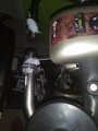
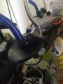
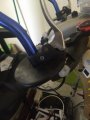
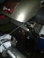
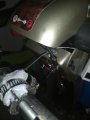
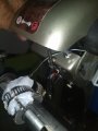
this shows the basic install. i want my wrists vertical, to lessen the damage to them when the tiller shakes. you can see the wigwag swings, the greater one is full throw, the lesser one is avail throw using 'brake' lever. it's not enough throw to get more than a slow crawl. i may be able to get the full throw by moving the cable end closer to the fulcrum. i'm not sure i have a drill bit to do that with. i will take an other day or so to try that. the wigwag spring is quite strong, and i was unsure my sore, weak hands could fight it longer term, but i think i can manage.
 

Attachments

DickCappels

Joined Aug 21, 2008
10,661
Are you planning to supply information necessary to complete your solution? If so, let’s keep the thread open so that when you come back with the information everybody participating in this thread will be notified.
 
Top