From Simulation to Breadboard gain drop

Thread Starter

YoGMan

Joined Sep 20, 2017
76
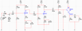
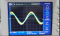
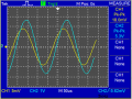
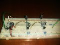
Hello guys, I built a pre-amplifier on Multisim but my gain dropped when I implemented the project on breadboard. I measured all the resistance and capacitor values ,then put on multisim to check. I properly connected my circuit on breadboard but still same problem. Any reasons for it ?d2018-11-02_215341.png


Mods Note:
The above circuit was copied from #10.
 

Attachments

BobaMosfet

Joined Jul 1, 2009
2,211
I would make sure you don't have a ground-loop on your breadboard. Breadboards are not of great quality and can create ground-loops just by poorly conducting. If you have more than one ground-wire anywhere, check the voltage difference between ground at your regulator or power-source, and each of your ground-points on the breadboard. If you see anything approaching half-a-volt or more, there's your loop.
 

Thread Starter

YoGMan

Joined Sep 20, 2017
76
I would make sure you don't have a ground-loop on your breadboard. Breadboards are not of great quality and can create ground-loops just by poorly conducting. If you have more than one ground-wire anywhere, check the voltage difference between ground at your regulator or power-source, and each of your ground-points on the breadboard. If you see anything approaching half-a-volt or more, there's your loop.
Hello, i will chek for ground loops but I think the main problem is the function generator itself being noisy at low amplitudes. my input should be 12mV pk-pk . Is there any way to input such low signal ?
 

crutschow

Joined Mar 14, 2008
38,458
my input should be 12mV pk-pk . Is there any way to input such low signal ?
You can use a two resistor attenuator reduce the signal level.
For example 1kΩ in series with 10Ω to ground will attenuate the signal by a factor of 101, thus 1.2V from the generator will generate ≈12mV across the 10Ω resistor.

Note that your schematic reference in post #3 gives me an error.
 

Audioguru

Joined Dec 20, 2007
11,248
A breadboard adds stray capacitance between its rows of contacts. The capacitance cuts high frequencies like the 5MHz you are amplifying.
Your schematic was posted wrong and does not show anything but an error message.

It looks like you are coupling the signals from one transistor to the next transistor with electrolytic capacitors that work poorly at your high frequency. Ceramic or film capacitors work much better. Why do you need the very high capacitance of your electrolytic capacitors at such high frequency?
 

ArakelTheDragon

Joined Nov 18, 2016
1,366
I can not open the circuit.

The simulation can have that disadvantage. I have had simulations with 1000V gain which is not possible under normal conditions.

Also if your power supply is "1VDC" in real life but on the simulation its higher, you can not expect a higher gain.
 

Thread Starter

YoGMan

Joined Sep 20, 2017
76
Hello everyone, Thanks so much for helping me out. It was actually my oscilloscope. I was using a cheap PC oscilloscope which gave me wrong values. I tested it at university and the circuit was fine, in fact i got EXACTLY like simulation :)
 

Attachments

Top