Frequency problems

Thread Starter

dmag0006

Joined Dec 8, 2010
17
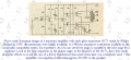
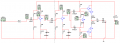
Hi, I have a project where I need to build an audio amplifier. This consists of 3 stages, two voltage amplifiers and a power amplifier. The circuit diagram is the one attached with most capacitors being equal to 4700μF. Everything has worked fine however I need to 'plot the frequency responce and find the bandwidth of the circuit'. I am having some problems doing so as I don't know how to plot the frequency responce. Can anyone please show me how to perform the analysis? If you do please try to be as basic as possible as I'm far from being an expert.:confused: Thanks!
 

Attachments

THE_RB

Joined Feb 11, 2008
5,438
I use a dual trace 'scope and a variable frequency sinewave generator. This is a very low tech system.

Inject a fixed amplitude sinewave in, say 1v peak to peak as seen on the scope. Set your scope vert resolution so 1v = 5 divisions.

Then view the amplifier output on the second scope trace (at the same time) use the vert adjuster trim to make the output also equal exactly 5 divisions.

So now you can see both the input and output sines, both are exactly 5 divisions high.

Then change the input frequency, you can read the frequency by the horizontal scope axis. You may sometimes need to "trim" the sine generator knob to keep the input voltage at 5 divisions high. (The goal is to inject the same signal height into the amp at all times)

If the amp output signal drops you have proof that that freq is being attenuated and you can draw it in a chart. For the majority of the frequencies there will be no attenuation so you can just see the scope results are ok, and you normally only need to chart the very low and very high frequencies where the amp starts to lose gain.

I know that sounds complicated but it's actually a very simple and easy thing to do!
 

Audioguru

Joined Dec 20, 2007
11,248
Why are there 10 current meters messing up your schematic?
Why doesn't the amplifier have any negative feedback like ALL amplifiers have?
Why isn't the amplifier DC-coupled like ALL amplifiers have used for about 50 years?
 

THE_RB

Joined Feb 11, 2008
5,438
That amplifier is not so bad AG? It has a couple of common emitter stages and a AB pushpull output, these are all pretty typical and AC coupling is fine.

It looks like many 10W to 50W guitar amps and PA amps etc I have seen over the years. Probably the most urgent improvement it needs is a trimpot to set the output bias current. ;)
 

Audioguru

Joined Dec 20, 2007
11,248
That amplifier is not so bad AG? It has a couple of common emitter stages and a AB pushpull output, these are all pretty typical and AC coupling is fine.

It looks like many 10W to 50W guitar amps and PA amps etc I have seen over the years. Probably the most urgent improvement it needs is a trimpot to set the output bias current. ;)
ALL half-decent audio amplifiers have plenty of negative feedback to reduce distortion so that it cannot be heard. This one has NO negative feedback so its distortion will sound horrible (like many guitar amps).
It also has too many coupling capacitors like this Philips transistor amplifier from 1955:
 

Attachments

THE_RB

Joined Feb 11, 2008
5,438
Thanks for that schematic! It's cute. I like the wiggly resistor symbols and the backwards-drawn NPN transistor symbols! I had never seen those before. :eek:

You're too fussy sometimes AG! Not every audio amp has to be a hi-fi amp! PA and intercom/telecom amps work better with very limited freq response and guitar amps work better with particular distortion characteristics and frequency response that varies with peak power levels etc.

Hi-fi is just ONE type of audio amp.
 

CDRIVE

Joined Jul 1, 2008
2,219
That's odd. The transistors are drawn as PNPs but they're connected polarities are definitely NPN. Odd looking resistors too!
 

Audioguru

Joined Dec 20, 2007
11,248
That's odd. The transistors are drawn as PNPs but they're connected polarities are definitely NPN. Odd looking resistors too!
You are absolutely correct!
I didn't notice that Philips drew the wrong positive power supply instead of using a correct negative power supply for the germanium PNP transistor amplifier.
 

CDRIVE

Joined Jul 1, 2008
2,219
The OC71 was a germanium PNP transistor. I think that whomever drew that schematic was confused.
You are absolutely correct!
I didn't notice that Philips drew the wrong positive power supply instead of using a correct negative power supply for the germanium PNP transistor amplifier.
Thank goodness.... Senior moments have become more frequent. I was beginning to think this was another one. :D
 

someonesdad

Joined Jul 7, 2009
1,583
I use a dual trace 'scope and a variable frequency sinewave generator. This is a very low tech system.
THE_RB is right. While low tech, it's a method folks have been using for generations. You can also measure the phase response with a little more work and plot it too if that's important to you. If you have a function generator with a sweep, you can generate the whole amplitude response with a single sweep. The attached picture is an example of an RC circuit's frequency response gotten this way.
 

Attachments

Top