FPGA based unknown circuit application

Thread Starter

mo.glmdi

Joined Aug 28, 2022
6
Hello Everyone.
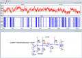
I'm analyzing a piece of circuit that have FPGA in its core to understand its operation. But I've encountered a part of this circuit that I have no idea about it. There is an input signal from a pick-up coil with 2.5V offset DC after amplification stage and a comparator that compare this signal with a 2.5VDC reference voltage and outputs a pulse train that just fluctuate like a noise. I'm wondering what is the main idea behind this section? Is it for noise removal? If yes, What is the main algorithm to do this?
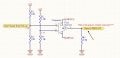
I attached the schematic of circuit in this post and really appreciate if anyone can help me to resolve this problem.
 

Attachments

WBahn

Joined Mar 31, 2012
29,978
Who knows? It depends on what the person that designed it is trying to accomplish. The same circuit can be used for lots of different things.

Why are you analyzing this?

Are you saying you have absolutely no idea what this thing is for? That, as far as you know, it might be a radio receiver or a radiation detector or a model rocket launch controller?

If so, then that again begs the question of what the point is in analyzing it?

Based on just the tiny bit of information provided, my first thought was that it might be related to doing frequency detection.
 

Ian0

Joined Aug 7, 2020
9,667
"Pickup coil" would tend to describe a sensor that detects a rotating ferrous part.
My guess (again based on very limited information) is that it is a tachometer.
 

Thread Starter

mo.glmdi

Joined Aug 28, 2022
6
Who knows? It depends on what the person that designed it is trying to accomplish. The same circuit can be used for lots of different things.

Why are you analyzing this?

Are you saying you have absolutely no idea what this thing is for? That, as far as you know, it might be a radio receiver or a radiation detector or a model rocket launch controller?

If so, then that again begs the question of what the point is in analyzing it?

Based on just the tiny bit of information provided, my first thought was that it might be related to doing frequency detection.
Thanks @WBahn. This is just part of an industrial sensor circuit that measure the displacement and I try to understand its designer idea to do this. As you mentioned, It's like a zero-crossing detector with DC bias of 2.5V, but there is no point in measuring frequency here, because coil signal itself is not intrinsically a periodic signal. My guess is, it can be a routine for creating error signal to compensate later in a closed control loop. But I'm not sure how we can do that in FPGA and how can add or subtract the final result to main signal!
 

Thread Starter

mo.glmdi

Joined Aug 28, 2022
6
"Pickup coil" would tend to describe a sensor that detects a rotating ferrous part.
My guess (again based on very limited information) is that it is a tachometer.
Thanks @Ian0. Yes guess right, It's related to a sensor but not a tachometer. It's just a high resolution linear displacement sensor.
 

ericgibbs

Joined Jan 29, 2010
18,766
hi mo,
It effectively rectifies any noise signals above the +2.5V threshold.
The Comparator is an open 'collector', so any noise is rectified and appears as a positive going logic level signal to the FPGA.
E
This simulation uses a simple Sine wave input to show the operation of the circuit.
E

EDIT: Added a Noise signal source

EG 1374.png
 

Attachments

Last edited:

Thread Starter

mo.glmdi

Joined Aug 28, 2022
6
hi mo,
It effectively rectifies any noise signals above the +2.5V threshold.
The Comparator is an open 'collector', so any noise is rectified and appears as a positive going logic level signal to the FPGA.
E
This simulation uses a simple Sine wave input to show the operation of the circuit.
E
View attachment 274894
Thanks @ericgibbs for your great simulation. You're definitely right. It'll rectify all the noises above ref voltage. but the main question here is what is the purpose of getting such pulse train that has a stochastic manner? and what is the key point of using that in FPGA?
 

Ian0

Joined Aug 7, 2020
9,667
Thanks @Ian0. Yes guess right, It's related to a sensor but not a tachometer. It's just a high resolution linear displacement sensor.
If it's a linear displacement sensor, either it counts magnetic as it passes a notched ferrous component, or it measures the amount of signal coupled between two coils.
If the latter, then there must be a drive signal for the coil somewhere.
 

ericgibbs

Joined Jan 29, 2010
18,766
hi mo,
Without knowing the full purpose of the FPGA project I cannot say, but if any form of analysis is carried out with the FPGA, I would expect it would require a Logic level input representation of the 'noise' signal.
E
 

Thread Starter

mo.glmdi

Joined Aug 28, 2022
6
If it's a linear displacement sensor, either it counts magnetic as it passes a notched ferrous component, or it measures the amount of signal coupled between two coils.
If the latter, then there must be a drive signal for the coil somewhere.
There is just one passive coil.
 
Top