FNA41560 overcurrent detection circuit

Thread Starter

sruthisindu

Joined Oct 14, 2022
5
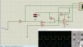
I am trying to decode a VFD board which uses FNA41560 inverter IC. It has an overcurrent detection circuit as shown in circuit below. The output signal Vout is given to microcontroller pin. What does the circuit signify ? What is it trying to compare?
 

Attachments

Ian0

Joined Aug 7, 2020
13,132
Are you really sure about R4 and R7? Nu, Nv and Nw are the negative supplies to the bridge, so R4 and R7 would be a current sensing resistor, in which case they would be fractions of an ohm.
The next stage looks like a current shunt amplifier, with the added feature of a capacitive load on an op-amp which is renowned for its ability to go unstable when driving a capacitive load.
 

Thread Starter

sruthisindu

Joined Oct 14, 2022
5
Are you really sure about R4 and R7? Nu, Nv and Nw are the negative supplies to the bridge, so R4 and R7 would be a current sensing resistor, in which case they would be fractions of an ohm.
The next stage looks like a current shunt amplifier, with the added feature of a capacitive load on an op-amp which is renowned for its ability to go unstable when driving a capacitive load.
Thankyou for pointing it out. The parallel combination of R4 and R7 gives a value of 0.3 ohm only. So, its the shunt resistor. But, how does the next stage measure the current ?
 

Ian0

Joined Aug 7, 2020
13,132
Thankyou for pointing it out. The parallel combination of R4 and R7 gives a value of 0.3 ohm only. So, its the shunt resistor. But, how does the next stage measure the current ?
Differential amplifier with gain of 15k/2k or 130k/2k (that doesn't seem right, either)
 

Thread Starter

sruthisindu

Joined Oct 14, 2022
5
Differential amplifier with gain of 15k/2k or 130k/2k (that doesn't seem right, either)
Simulation shows a mere comparator output for the input AC signal with respect to reference voltage 0V. Converted the voltage source of 4 A to a current source 1.2 V and removed the output capacitor. Still unclear how comparator output senses current.
 

Attachments

Ian0

Joined Aug 7, 2020
13,132
The circuit implementation is similar to the one in this post
http://ardupiclab.blogspot.com/2019/07/a-simple-circuit-for-measuring.html
But the method of obtaining correction factor for current calculation is vague.
Similar, but the ArduPicLab circuit is sensible - the resistors on the differential amplifier are in identical pairs, there is a sensible method of setting the zero-point and the op-amp isn't being asked to drive a big capacitive load which would make it unstable.
What do you mean by correction factor?
 
Top