Fm transmitter circuit

Thread Starter

lokesh2310

Joined Feb 23, 2024
5
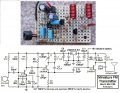
I am trying to implement a general fm transmitter similar to the schematic i found on internet.

my implemented circuit
circuit.jpg

schematic found on internet

schematic.png


when i implemented the design i found out that even if i remove the lc tank the circuit provide an carrier of aroung 70Mhz changing the value of lc tank does not change the value of carrier generated. i want to increase the carrier to around 90MHz. apart from this i am not able to understand how this circuit is working. because according to schematic the circuit should work only when lc tank is connected as it will work as a oscillator.
Can anyone please help me to understand this circuit and plausible reason how it is working and how to get the desired frequency. Any source(book,website,tutorial,etc) where i can learn about these circuit in detail like circuit analysis.

without lc tank schemetic:-
circuit2.jpg

waveform obtained on oscilloscope
waveform.jpg
 
Last edited by a moderator:

Alec_t

Joined Sep 17, 2013
15,105
Welcome to AAC!
All those flying wires, plus the breadboard's conductive tracks, add unknown inductance to the circuit. The breadboard also has inevitable inter-track capacitance. With the effects of all those parasitic components it's not surprising that oscillation occurs at some weird frequency (if at all).
For reliable high-frequency circuits, breadboard construction is unsuitable.
 

Thread Starter

lokesh2310

Joined Feb 23, 2024
5
Welcome to AAC!
All those flying wires, plus the breadboard's conductive tracks, add unknown inductance to the circuit. The breadboard also has inevitable inter-track capacitance. With the effects of all those parasitic components it's not surprising that oscillation occurs at some weird frequency (if at all).
For reliable high-frequency circuits, breadboard construction is unsuitable.
but why it is always giving me frequency around 72MHz
and can you please share some resource to understand the circuit better
 

MrChips

Joined Oct 2, 2009
34,629
There is too much stray capacitance on a solderless breadboard.

Try a technique on copper laminate called Manhattan style prototyping. Notice that the circuit nodes are small square pieces of copper laminate glued on top of the supporting ground plane.

1714062417154.png


Another simple technique is to cut out islands to creates circuit nodes as shown below.
1714062376090.png
 

Wendy

Joined Mar 24, 2008
23,798
The circuit itself is a variation of the common base amplifier design. I would not use protoboards for anything over 500K Hz. For all of the reasons that have all already been mentioned.
 

Audioguru again

Joined Oct 21, 2019
6,826
The supply voltage of only 3V is too low for most electret mics that are powered from the 4.7k resistor.
The mic draws a current of up to 0.5mA and uses a minimum voltage across it of 2V.
0.5mA x 4.7k= 2.35V then the mic gets only 3V-2.35V= 0.65V but at such a low voltage its current will be less than 0.5mA and the mic probably will not work.

The simple circuit needs an RF amplifier transistor to isolate the oscillator tuning capacitor from the antenna that changes its capacitance (changing the radio frequency) when something moves towards or away from the antenna.

The circuit also needs a voltage regulator to prevent the radio frequency from changing as the battery voltage runs down.

It also needs an audio preamp with pre-emphasis (treble boost) like all FM radio stations use to match the de-emphasis used in all FM radios.
 

Thread Starter

lokesh2310

Joined Feb 23, 2024
5
can i use a varoboard or General purpose pcb for soldering these componenets.
And can someone please refer a book from where these type of circuit are derived as I am not able to understand the analog working of this circuit.
 

Janis59

Joined Aug 21, 2017
1,894
Rather popular circuit for extra small power simplest of simple transmitters at distance of dozen meters. Generator works in circuit of common base, therefore that capacitor C1 between base and gnd. Thus, it must be a FAST capacitor not a rolled paper type. Sigal frequency is selected by means of combination of L1C2 - hopefully Thomson formula You know. The positive back loop is organized by C3 between collector and emitter. It must be individually adjusted to value when generation amplitude is starting sharply to fall, but still is large. If loop is too stringent, then there are too much 3rd harmonics and ample phase noise, but if too weak then amplitude is small and frequency instable. Resistor is the load where back loop signal is added in, but electret microphone changes the transistor biasing thus changing the amplitude modulation deapth. So simple.
 

Thread Starter

lokesh2310

Joined Feb 23, 2024
5
Rather popular circuit for extra small power simplest of simple transmitters at distance of dozen meters. Generator works in circuit of common base, therefore that capacitor C1 between base and gnd. Thus, it must be a FAST capacitor not a rolled paper type. Sigal frequency is selected by means of combination of L1C2 - hopefully Thomson formula You know. The positive back loop is organized by C3 between collector and emitter. It must be individually adjusted to value when generation amplitude is starting sharply to fall, but still is large. If loop is too stringent, then there are too much 3rd harmonics and ample phase noise, but if too weak then amplitude is small and frequency instable. Resistor is the load where back loop signal is added in, but electret microphone changes the transistor biasing thus changing the amplitude modulation deapth. So simple.
can i use aux cable connected to my mobile phone in place of electret microphone.
 

MisterBill2

Joined Jan 23, 2018
27,193
It has already been mentioned about the circuit on a massive breadboard array being unsuited. Radio Shack used to sell a wireless microphone that utilized an electret microphone cartridge, and the whole package would be powered by two AA cells in series. It functioned OK at 20 feet, and the sound was OK, depending on the receiver. So some electret mics will perform adequately with 3 volts or less. They certainly are not all the same.
 

Audioguru again

Joined Oct 21, 2019
6,826
19 years ago I saw a post in another forum about a very simple FM transmitter similar to this one that also did not work.
Since the causes of its problems were obvious then I fixed them and built mine compactly on Veroboard.
It worked perfectly and sounded very good.

BUT it was illegal because its output power was strong enough to cover-up some of the many FM radio stations around me.
The only unused space on my FM dial was being used sometimes by a low power religious station on the other side of my city.

A neighbor saw the Rf COPS (with the FM antenna on it) slowly driving near my street. They were probably looking for me.

Fairly recently, Silicon Chip magazine in Australia showed their 3rd FM stereo transmitter project (Micromitter) based on a chip made by Rohm. Silicon Chip magazine also sold a kit for it. The IC is not made anymore. The transmitter circuit used an attenuator on its antenna output making is range low and legal.

Here is my illegal FM transmitter:
 

Attachments

Thread Starter

lokesh2310

Joined Feb 23, 2024
5
cn
19 years ago I saw a post in another forum about a very simple FM transmitter similar to this one that also did not work.
Since the causes of its problems were obvious then I fixed them and built mine compactly on Veroboard.
It worked perfectly and sounded very good.

BUT it was illegal because its output power was strong enough to cover-up some of the many FM radio stations around me.
The only unused space on my FM dial was being used sometimes by a low power religious station on the other side of my city.

A neighbor saw the Rf COPS (with the FM antenna on it) slowly driving near my street. They were probably looking for me.

Fairly recently, Silicon Chip magazine in Australia showed their 3rd FM stereo transmitter project (Micromitter) based on a chip made by Rohm. Silicon Chip magazine also sold a kit for it. The IC is not made anymore. The transmitter circuit used an attenuator on its antenna output making is range low and legal.

Here is my illegal FM transmitter:
can you explain the working of your radio why there is the same circuit around Q3 BJt as aroun Q2 Bjt
 

Audioguru again

Joined Oct 21, 2019
6,826
cn

can you explain the working of your radio why there is the same circuit around Q3 BJt as aroun Q2 Bjt
Q1 is the audio preamp with pre-emphasis.
Q2 is the RF oscillator same as the simple circuit you showed. My C7 and R7 provide the positive feedback.
Q3 is the RF amplifier that isolates the oscillator from variable capacitance at the antenna.
 
Top