Flyback with 2 of the exact same secondary windings getting two different voltages

Thread Starter

jlawley1969

Joined Feb 22, 2021
97
hi me again.
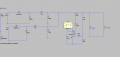
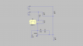
So I am using TNY290 and a 749118205 for two 5V outputs. I have included a schematic from the application notes that shows multiple outputs. Okay so I have it set up so that both outputs go through their respective 20kOhm resistor to a divider of a 10kOhm resistor to ground and this feeds the reference pin on the TL341. But I have only one feeding the opto isolator and it is that one that is being properly regulated. The one that is not feeding the opto isolator is reading 3.90V at no load on the either output and 7V with load on the other. Mind you all the components on the protoboard are the exact same for both outputs. (ive inlcuded an example of what I am trying to show from ltspice ignore the item name for the opto that was just whatever)

I can get both outputs to be the same if I feed both outputs to the optoisolator but I dont understand why I should have to do that the schematic from the application notes does not do that and the notes also make no mention of preload or anything like that.
I need both to be close as possible to 5-5.5V for most usb devices to accept it and start charging
 

Attachments

Ian0

Joined Aug 7, 2020
9,817
That application note has multiple outputs of different voltages, achieved by stacking the windings in series.
How have you connected the windings?
 

Thread Starter

jlawley1969

Joined Feb 22, 2021
97
How do you do that? Two 100 ohm resistors?
Windings do not like to be run with out a load. Try putting a 1/4 watt load on each.
The two windings will need to be tightly coupled to run like this. I bifilar wind.
View attachment 250136
I had them both feeding one 47Ohm resistor. I will try two separate resistors.

This is just a question for my understanding: does the fact that the output is connected to the optoisolator act as a load?
 

Thread Starter

jlawley1969

Joined Feb 22, 2021
97
That application note has multiple outputs of different voltages, achieved by stacking the windings in series.
How have you connected the windings?
I see what you mean. I do NOT want different output voltages just to be clear it was just an example
I dont have mine stacked I am using the attached transformer. I have a separate diode attached to pins 3 and 5. Then pins 6 and 4 are not connected and used as ground for their respective winding.

I however did briefly try connecting 6 and 4 and it did not seem to change anything
 

Attachments

ronsimpson

Joined Oct 7, 2019
3,037
You have two windings. One loaded and one not loaded. The Diode Capacitor makes a peak detector. The unloaded output will have a voltage from the peak of the ring as shown in red. The loaded output will set down on the body of the waveform. Shown in green.

If the error amplifier (TL431) is looking at the loaded output it will be at 5V and the unloaded one will be at 6V. But if the error amp is looking at the unloaded output the wave form will be smaller so the red output is 5V and the green line is at 4V.

In your case you are looking at the average of the two outputs so 5V is in-between Red and Green.

It is common to load all windings so the output is not sitting at the top of the ring but close to the body of the wave form. (try 1/4 watt)
1634170181364.png
I hope you can see how the output voltage comes from the wave form. The ring comes from leakage inductance inside the transformer.
RonSimpson
 

Thread Starter

jlawley1969

Joined Feb 22, 2021
97
You have two windings. One loaded and one not loaded. The Diode Capacitor makes a peak detector. The unloaded output will have a voltage from the peak of the ring as shown in red. The loaded output will set down on the body of the waveform. Shown in green.

If the error amplifier (TL431) is looking at the loaded output it will be at 5V and the unloaded one will be at 6V. But if the error amp is looking at the unloaded output the wave form will be smaller so the red output is 5V and the green line is at 4V.

In your case you are looking at the average of the two outputs so 5V is in-between Red and Green.

It is common to load all windings so the output is not sitting at the top of the ring but close to the body of the wave form. (try 1/4 watt)
View attachment 250194
I hope you can see how the output voltage comes from the wave form. The ring comes from leakage inductance inside the transformer.
RonSimpson
I believe I understand the concept now and I will add a quarter watt load.

One question, is the unloaded side acting as peak detector because it does not have a load that would discharge the diode's capacitor?
 

ronsimpson

Joined Oct 7, 2019
3,037
One question, is the unloaded side acting as peak detector because it does not have a load that would discharge the diode's capacitor?
Yes. There is some energy in the "ring" that pushes up the voltage. That energy or part of that energy could be burned up in a load resistor. I only guessed "1/4 watt". Even if you use up half of the energy it will really help your unloaded regulation.
should I be running both outputs to the opto isolator through their own resistor?
It only cost you 1 resistor. I see error amplifiers watching two or three voltages many times. (+5V and +12V for computer and hard drive) In those cases only one supply for the opto. In your case I would probably use two resistors. If the opto is on output A only then I would put a larger dummy load on output B. (so both sides see about the same current)
 

Thread Starter

jlawley1969

Joined Feb 22, 2021
97
Yes. There is some energy in the "ring" that pushes up the voltage. That energy or part of that energy could be burned up in a load resistor. I only guessed "1/4 watt". Even if you use up half of the energy it will really help your unloaded regulation.

It only cost you 1 resistor. I see error amplifiers watching two or three voltages many times. (+5V and +12V for computer and hard drive) In those cases only one supply for the opto. In your case I would probably use two resistors. If the opto is on output A only then I would put a larger dummy load on output B. (so both sides see about the same current)
hmm the pre load helps but still slipping more than I can tolerate and then heat would become an issue if I went to a higher preload

I am now wondering if I could pass each secondary winding through a diode filter them then combine them THEN break off again.
The reason I would want to do this instead of using a single secondary winding is that it is smaller to use the one I am now

see attached for what I mean
 

Attachments

ronsimpson

Joined Oct 7, 2019
3,037
You can parallel the two windings and pretend it is one at higher current. (use one diode)
You can use two diodes, one cap and one inductor.
You can do what is shown.
There are many ways that all work.
1634234026686.png
 
Are you certain that both windings are in flyback? I have seen examples where one winding is in flyback, and the other "forward". The thing works, but with incorrect voltages.
 

UweX

Joined Sep 2, 2020
33
According to the transformer datasheet they are. The datasheet of the transformer specifies the wiring resistance. I cannot recognize in the schematic, if they are taken properly into account (L2 and L3) . The other important thing is, that they winding resistance is just a DC-value. Skin effect at switching frequency may drive the voltage drop at different load current already higher.
 

ronsimpson

Joined Oct 7, 2019
3,037
Are you certain that both windings are in flyback?
If one winding was backwards:
The winding in flyback would regulate. The winging in feed forward will simply pass the input voltage through by the turn ratio. It would have a 1/19 the input voltage. Change the input voltage and the backwards winding will change by the same percentage.
 

UweX

Joined Sep 2, 2020
33
Above we have an excerpt of the transformer datasheet. The winding orientation is marked there. Also is written in the text, that 3 and 5 are connected to the diodes, so the windings have the same orientation.
The high isolation voltage between the secondary windings indicate, that they are not bifilar windings as you recommended. So the magnetic coupling between secondary windings is not at 1.0.

I didn't find a note about the maximum load current you want to achieve per winding. But including winding resistance in the simulation may already help clarifying the maximum matching of the voltage under different load conditions.
 
Top