Facebook
 Google
 GitHub
 Linkedin
Hi,
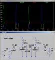
I've bought a cheap unipolar stepper motor for the purpose of learning how to work with steppers. It is wired such that there is a single common for all 4 phases (schematic).
Now I'm trying to figure out how to arrange fly-back diodes around a stepper. According to this source you shouldn't put diodes across the windings or generative braking will occur when the winding is shut off. Near the bottom of the page below "Simpler smart brakes" it says you should put the diodes across the transistor, but I don't see how D2 protects Q1 and I can't get it to work in a simulation.
Any thoughts on this? Or regardless of the above how would you arrange fly-back diodes in a stepper motor circuit?
Attachments
-
 87.9 KB Views: 52
 -
2 KB Views: 17
 (Where did you get the idea that it reverses?)