Floating OPAMP to high voltage rail

Thread Starter

M_Mac1992

Joined Jul 11, 2018
2
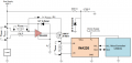
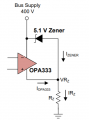
I am currently having difficulty understanding the operation of this circuit. From my understanding the Zener diode provides a 5.1V voltage drop resulting in VRz = (400-5.1) = 394.9V. Meaning the OPAMPs + rail is 400V and the - 349.9V how does this supply the device, my intial thoughts are it takes the potential difference of the to rails (v+ - v-) = 5.1V but is this correct ?
 

Attachments

OBW0549

Joined Mar 2, 2015
3,566
...my intial thoughts are it takes the potential difference of the to rails (v+ - v-) = 5.1V but is this correct ?
Yes.

This circuit simply sets the op amp's total supply voltage (i.e., the voltage difference between its V+ and V- supply terminals) at 5.1 volts. Whatever voltage is applied to the V+ terminal, the V- terminal will be 5.1 volts lower.
 

crutschow

Joined Mar 14, 2008
34,284
So the input and output of that op amp can go from 349.9V to 400V (for a rail-rail op amp).

Do you have a use for this circuit?
 

ebp

Joined Feb 8, 2018
2,332
It is essential that the resistor Rz be a value that, with 395 volts across it, allows a current equal to that required by the amplifier and its load plus typically a milliamp or so for the zener. The minimum current required through the zener depends on the specific type use. A typical 500 mW zener such as a 1N5231B is characterized at 20 mA, which is far too high for a circuit like this because it would cause 8 W of dissipation in the resistor, but if the datasheet is consulted it looks OK at about 5.0 volts at 1 mA. There are a few zeners rated for lower power available and they might allow lower current - perhaps a few hundred microamps.

If the amplifier load current flows from the amp output to the amp's negative supply, then that current will also flow through the resistor but not through the zener. This means care is necessary to be sure the resistor is rated for adequate power. For example, if the amp required 1 mA, the load current was 2 mA and the zener current was to be 1 mA, 4 mA would flow through Rz which would require a power rating of at least 4 mA x 395 V = 1580 mW. A 2 W resistor would be suitable. The OPA333 supply current is only about 20 µA, which is helpful for this sort of circuit.
 

dl324

Joined Mar 30, 2015
16,846
Yes it is a section of a current monitor for a 400V bus designed by TI.
If you are working with these voltages, you need to be aware of the maximum working voltage for all components. For commonly used resistors, maximum working voltage is on the order of 200-250V.

Typical 1/2 to 3W are on the order of 350V.
 

crutschow

Joined Mar 14, 2008
34,284
You can increase the total resistor working voltage, of course, by using two or more equal value resistors in series to get the desired total resistance.
 

dl324

Joined Mar 30, 2015
16,846
You can increase the total resistor working voltage, of course, by using two or more equal value resistors in series to get the desired total resistance.
A common practice if you know enough to be concerned about it.

The schematic above shows a single resistor. If it's supposed to be rated for high voltage, it might have been noted elsewhere. Some military grade resistors have 500V working voltages.
 
Top