Flip flop ic

Thread Starter

Hellerx44

Joined Apr 6, 2021
52
Hi
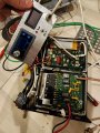
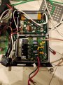
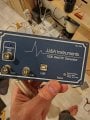
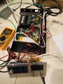
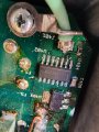
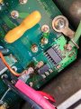
I bought an rf 1000w amplifier from ebay for 30$ from a seller, it was hell cheap for this kind of amplifier, when I got it I understood the reason, it was a device controlled by pc software, and I couldn't find the software for it as the company is permanent closed. Now I managed to by pass the electronics controller as the power supply triggered by low voltage between 1.5v to 1.7v. And success, , after I built new front panel and voltage voltmeter and test every thing, it stopped working, I figured out that the amplifier has a dual d type positive edge triggered flip flop, tried to conect pin 14 and 3 it worked for a second then stops agine , how to bypass this flip flop ic? Or how to rest it ?
 

Attachments

MisterBill2

Joined Jan 23, 2018
27,508
The only thing that those photos tell us is that none of the parts shown have burned up. For anybody to provide any sort of useful advice on making the "amplifier" work, we need to see the circuit diagram, including the power portion and probably the amplifier section.
 

sagor

Joined Mar 10, 2019
1,049
If those 4 transistors in the picture are the finals of the amplifier, no way it is a 1000W amplifier, at least not for regular modes. It may be a pulse amplifier, where duty cycle is 1 in a 1000 or something similar. Hint: it was "PC controlled" - usually means intermittent operation. There is no massive heatsink, and a small PC type of fan is not going to cool much at high power levels. Also, the tuned circuit will be fixed to one frequency/band and not adjustable.
If the power supply is in the 12-13VDC range, the wire leads are too small for 1000W. Maybe they will handle 100W. Even then, the heatsinking is too small. If the power supply is in the 50-60V range, it may run a bit more power as the wires can handle the current at those voltages.
Bottom line, I think you got something different than what you were expecting....
 

Thread Starter

Hellerx44

Joined Apr 6, 2021
52
If those 4 transistors in the picture are the finals of the amplifier, no way it is a 1000W amplifier, at least not for regular modes. It may be a pulse amplifier, where duty cycle is 1 in a 1000 or something similar. There is no massive heatsink, and a small PC type of fan is not going to cool much at high power levels. Also, the tuned circuit will be fixed to one frequency/band and not adjustable.
If the power supply is in the 12-13VDC range, the wire leads are too small for 1000W. Maybe they will handle 100W. Even then, the heatsinking is
You are right this is 1000w pulse, 200w cw.
The frequency is from 700kh to 5mhz
Check the attached file
Later when I get home I will attach some pics
 

Attachments

schmitt trigger

Joined Jul 12, 2010
2,088
I was going to comment “typical Chinese crap”, until I noticed in one of the board photos: Made in the USA.

What I assume it could be happening: the amp is shutting itself down because of excessive VSWR. It is an RF amp after all.
 

Thread Starter

Hellerx44

Joined Apr 6, 2021
52
I was going to comment “typical Chinese crap”, until I noticed in one of the board photos: Made in the USA.

What I assume it could be happening: the amp is shutting itself down because of excessive VSWR. It is an RF amp after all.
No , the device output is conected to 500w dummy load and vswr meter. The issue is the flip flop ic ,If I connect pin 14 to pin 3 it works for a second and off agine.
 

MisterBill2

Joined Jan 23, 2018
27,508
actually, if those transistors can handle ten or 15 amps, and if the circuit is powered at 120 volts DC, it could certainly be a "1000 watt INPUT" amplifier. Some of them are rated that way. In fact, 50 years ago it was the standard way of rating RF amplifiers, because DC power in is simple to measure.
 
Top