Facebook
 Google
 GitHub
 Linkedin
Hello,
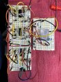
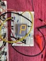
I’ve got a project for a display that I was asked to provide with a fake broken/ripped apart clock. On the face of the clock will be a word made of letters on each of the 4, 7 segment displays. 4 letters on 4 displays. A total of 16 LED segments will be lighted. Yellow segments I want to operate at 6 vdc, each less than .02ma. I’ve found I want to use a 220 ohm resistor in series with each segment for good brightness. Here’s the rub. I want the whole word to flicker randomly as if the clock has been broken enough to stop working at any moment.
Any ideas? I want to use a 6vdc, 1000ma wall wort and some sort of circuit in series to nicely flicker the power, hence flicker the clock?
Any help would be super helpful
Thanks.