Flame sensor circuit

Thread Starter

seayaker

Joined Jan 27, 2009
98
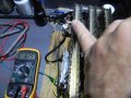
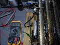
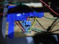
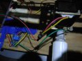
Can anyone show me how to make a circuit like the one in this video? I need to increase the signal from a flame sensor rod to put out 3 volts DC so that it will activate the actuator that opens the gas valve. The rod only puts out a slight amount of voltage and current when a flame is applied. Or if anyone knows where I could get a module that would work.
https://www.youtube.com/shorts/Bl2hGox1lcs
 

Sensacell

Joined Jun 19, 2012
3,780
A flame looks like a very high resistance, maybe 100 Meg Ohms, it's not going to generate any voltage on it's own.

Apply a relatively high voltage across the flame an look for a very small current flow.
 

Thread Starter

seayaker

Joined Jan 27, 2009
98
How much current does the actuator require at 3 volts?
My other question is: how do you get the flame to start with if the valve is closed?
Thanks I tried to measure the current, it fluctuates but is very slight. I am lighting it manually so if I hold the lighter over the sensor rod and the burner which is grounded it will complete the circuit. I just want this for safety so if the flame blows out the gas will shut off.
 

MisterBill2

Joined Jan 23, 2018
27,394
Actually, at least some flames show a fairly low resistance. So a simple comparater with a pull up resistor should work. A 2.7 meg resistor pull up to 5 volts should be adequate. There are flame sensor modules available, also. Of course, a blue flame probably has more resistance than a yellow one.
 

Ya’akov

Joined Jan 27, 2019
10,226
My other question is: how do you get the flame to start with if the valve is closed?
Flame sensors are used as a safety measure for standing pilots. The pilot has a different source of gas than the burner and the flame sensor is used to detect that there is a pilot to ignite the gas when the burner is called for—no flame, no flow to the burner.
 

MisterBill2

Joined Jan 23, 2018
27,394
Quite a few recent gas using appliances use an electrically ignited pilot light arrangement to avoid the fuel consumption of a standing pilot light. So they have two gas valves, the first valve operates along with the pilot igniter system, which switches off when the pilot flame is detected. That is the scheme used for many RV absorbtion refrigerators. After the pilot flame is sensed then the main gas valve can operate. In addition, some other systems that do have a standing pilot flame use the flame sensor system to enable the main gas flow valve. That scheme is used in place of the thermocouple pilot sensor, and in some cases it is in addition to that sensor.
And, additionally, some appliances use direct ignition of the main gas flow, with the sensor needing to detect the flame within a very short time after the gas flow is started. The igniter system switches on with the main gas valve and the flame sensor must detect the flame within a second or two, or the gas valve is switched off, while the air blower continues to operate for a purge cycle time.
 

Thread Starter

seayaker

Joined Jan 27, 2009
98
Quite a few recent gas using appliances use an electrically ignited pilot light arrangement to avoid the fuel consumption of a standing pilot light. So they have two gas valves, the first valve operates along with the pilot igniter system, which switches off when the pilot flame is detected. That is the scheme used for many RV absorbtion refrigerators. After the pilot flame is sensed then the main gas valve can operate. In addition, some other systems that do have a standing pilot flame use the flame sensor system to enable the main gas flow valve. That scheme is used in place of the thermocouple pilot sensor, and in some cases it is in addition to that sensor.
And, additionally, some appliances use direct ignition of the main gas flow, with the sensor needing to detect the flame within a very short time after the gas flow is started. The igniter system switches on with the main gas valve and the flame sensor must detect the flame within a second or two, or the gas valve is switched off, while the air blower continues to operate for a purge cycle time.
Yes I know, I looked at some of the RV furnace control boards but this is much simpler. Since I plan to light the burner manually with a long butane lighter all I need is the one valve to shut off if the flame were to blow out. I have a burner from a tankless LPG water heater, it has the actuator gas valve. I tested it, when I apply 3v the valve opens and I can light the burner. I also have the sensor rods there were 3, one was probably the igniter it was quite dirty, probably why it no longer worked. Anyway If I can get the tiny signal from the flame sensor to apply 3v to the actuator it will work.
I don't know much about electronics all I have is a multimeter and a soldering iron. The comparator circuit makes since but I wouldn't know what components to get. My meter says it uses 0.22 amps to open the valve , please let me know If this - ( AD620 Microvolt MV Voltage Amplifier Signal Instrumentation Module Board } will work.
Thanks for responding.
 
Last edited:

geekoftheweek

Joined Oct 6, 2013
1,429
Flame sensors are used as a safety measure for standing pilots. The pilot has a different source of gas than the burner and the flame sensor is used to detect that there is a pilot to ignite the gas when the burner is called for—no flame, no flow to the burner.
Flame sensors are a safety measure for all flammable gas powered appliances. With an electronic ignition such as a modern furnace there is a small window of time between when the igniter is powered, the gas valve is commanded open, and the flame sensor is checked for the igniter to do it's job. If there is no flame detected after a gas valve is open for a set amount of time the valve will close and your LED will blink a code.

With a standing pilot they are often an expanding gas, alcohol, or such that hold open the safety in the valve when heated so the main burner can light. Standing pilots are more common with purely mechanical valves and appliances, but there's probably some with electric valves also.

Edit... I just realized all this was more or less covered in #8
 

Thread Starter

seayaker

Joined Jan 27, 2009
98
I got this - AD620 Mirco Milli Volt Signal Amplifier
I have it connected to a 12 v battery. When I hold a lighter so the flame touches both the burner which is connected to ground and the flame sensor which is connected to the + output I can get it to read 3v briefly. When I touch the burner and sensor with my finger it will stay at 3v but will not output enough power to open the solenoid. What do I need to get it to open the solenoid? If I connect a 3v battery to the solenoid it works, my meter says it draws 0.22 amps, what do I need to do to get it to open when I apply a flame?
 

Attachments

MisterBill2

Joined Jan 23, 2018
27,394
Probably, to switch on the power to operate the solenoid you need a switching transistor. In this case it will be a mosfet device that is switched into conduction when the gate is biased up to the 3v3 output of the flame sensor is active. The source terminal will tie to the common negative supply terminal, while the drain will connect to one side of the solenoid,with the other terminal of the solenoid connecting to the positive supply.
Is there any information or specifications sheet that came with that module?? That might tell the output current rating?
 

MisterBill2

Joined Jan 23, 2018
27,394
Given that the module output is from an LM358 configured as a voltage follower following an instrument amplifier, it is unlikely that the change in voltage out will be fast enough to require that spike clamping diode. And the circuit shone looks like what I suggested, so THANK YOU to sghioto!
 

MisterBill2

Joined Jan 23, 2018
27,394
Using a mosfet transistor it will be the output voltage that matters, not the current. There needs to be enough voltage to provide full saturation for the 220 MA current.
 
Top