Facebook
 Google
 GitHub
 Linkedin
Its hard for me to follow everything you're saying with my knowledge but you explained it well, I thought that showing variables as switches was the way you were supposed to on the simulator but I changed it to just a text box. Let me know what you think now, thanks!
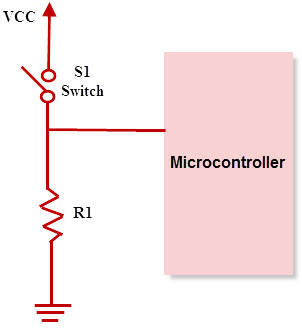
Edit: I can draw up gate diagrams using the basic gates pretty well by using the order of precedence even with moderately hard equations like in my lab. Im also pretty good with the truth tables. However, the main problem I'm having is understanding how it works with the chips, power, ground, switches, led, resistors (hands on stuff) ect as I have not had ANY experience with even basic wiring or any of that stuff. I guess the logic behind it is what confuses me right now like in the post above I didn't know that you needed resistors or what exactly they do and where to place them. It is only my first week of getting into this stuff but I want to try and get ahead and you guys are helping me out so thanks!
(I'm getting an analog and digital design trainer with the 7400, 7402, 7404, 7408, and 7432 chips with wires this week so I can start learning how to apply it hands on.. Id love to get suggestions on what else I should get to help out as well)
Hi,
Yes that looks very good
")
That takes you through the first step...going from equation to symbolic logic. Once you get that for any circuit, then you can move on to the actual implementation which can take many forms such as CMOS, TTL, LSTTL, ALSTTL. FTTL. HCMOS, HCTTL, ECL, too many to mention them all. In each of these cases you could use the same symbolic logic drawing, but there will be differences for inputs if you use switches, and power supply differences, and differences if any clock inputs are switched. So your first step is to convert the equation to logic symbols, then start to think about the logic family that best suites the design task. You can then start to fill in the details of what other parts you might need like pull up or pull down resistors, and then start to figure out the actual physical wiring scheme which may require some thought about how long a given copper trace can be. So going from the symbol diagram to physical layout requires a different thought process.