Facebook
 Google
 GitHub
 Linkedin
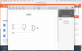
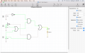
That's the idea. Now,First chip I think I got to work on the simulator! good way to end the night. Ill be doing more tomorrow with the other gates/chips (I know this is ridiculously basic but at least its something)
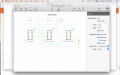
- add a resistor to the bottom of your LED (set it to 470 ohms),
- then connect other end of resistor to the ground wire below it.
Then you will see the LED light up instead of just turn Green outline. The green outline color means positive voltage is on that component or that wire.


")