First circuit attempt

Thread Starter

shivasage

Joined Jan 12, 2020
14
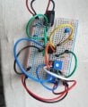
Hello all. I am attempting to create a circuit on a breadboard following this schematic. I've never done this before, thus I have little confidence that I did it correctly. However, I did my best. Here's a picture of the breadboard. Does it look okay? The only thing missing is the sensor which will be connected to ground and 18h.


Mods Edit:
Please upload the file to our forum, otherwise when the links is lost and the circuit will be lost too.
 

Attachments

Thread Starter

shivasage

Joined Jan 12, 2020
14
I could make a better critique of your circuit if I knew what it was supposed to do with sensor (why type?) signal.
Apologies. The point of the circuit is to use a FlexiForce force sensitive resistor to control output voltage from a range of 0 to +5V. I will press on the sensor with my finger. It is for a musical implementation so exact accuracy is not required. However, trimmers have been added to get as close to 0 to +5V as possible, with 0 output being when I am applying no pressure, and +5V being when I apply maximum pressure.

I spent a long time making the schematic, with help from people on this forum and another, so I'm not looking to change anything about it. I'm just looking for help with regards to turning a schematic into a physical circuit. Some parts of it were confusing to me as I've never studied electrical engineering. Of course the quickest test would be to actually test it, which I plan on doing, I was just slightly afraid of something getting fried when I plug in the 9V if I wired it incorrectly.
 

Audioguru again

Joined Oct 21, 2019
6,691
The (-) input pin of an opamp is very sensitive then the wire to your sensor will pickup a lot of interference.
The messy wires all over the place on your breadboard are much too long and will also pickup interference.

Instead of setting the reference voltage for the opamp (+) input and the offset voltage from the +9V that is not regulated, why not set them from the +5V that is regulated?

You did not tell us the resistance range of your sensor, then you might need to turn the gain pot to a resistance so low that the opamp will not work.
 

Thread Starter

shivasage

Joined Jan 12, 2020
14
The (-) input pin of an opamp is very sensitive then the wire to your sensor will pickup a lot of interference.
The messy wires all over the place on your breadboard are much too long and will also pickup interference.

Instead of setting the reference voltage for the opamp (+) input and the offset voltage from the +9V that is not regulated, why not set them from the +5V that is regulated?

You did not tell us the resistance range of your sensor, then you might need to turn the gain pot to a resistance so low that the opamp will not work.
The +9V will be coming from a regulated power supply (Truetone 1 SPOT), so that should be just as good as the LM78L05, yeah? (By the way I mislabeled the regulator on the schematic as LM7805, it's actually a LM78L05.)

The resistance of the sensor is basically infinite (5M ohms) with no pressure, and gets down to about 20k ohms with maximum force of 25 lbs.

How should I go about minimizing the interference caused by wires? If I finalize this project, it will be in an enclosure, so that will help, but while I'm prototyping with the breadboard, what can I do? All I can think of is shortening the jumper wires.
 

Dodgydave

Joined Jun 22, 2012
11,302
Your 47K is 56K ,ideally you need to get rid of the link wires, and put the resistors and caps as closed to the OP amp.
Which op amp pin is the input sensor going to?
 

Thread Starter

shivasage

Joined Jan 12, 2020
14
Your 47K is 56K ,ideally you need to get rid of the link wires, and put the resistors and caps as closed to the OP amp.
Which op amp pin is the input sensor going to?
Good catch. I must have mislabeled it. With that voltage divider configuration I ended up with the desired reference voltage of +1V.

The input sensor will be connected to the opamp (-) input, as shown on the schematic. Is that what you mean?

How much error is caused by the wires? Is it enough to make it impossible to test 'accurately'?
 

Audioguru again

Joined Oct 21, 2019
6,691
You should us a shielded audio cable between the sensor and the circuit to block the 60Hz AC interference caused by electrical wiring that is all around you, unless you are far from electricity.

Since the contacts on a solderless breadboard are intermittent and the wires all over the place and rows of contacts pickup interference and have capacitance between them all, I solder prototypes together on stripboard with most of the parts connected together by the strips plus a few soldered very short jumper wires.
 

Thread Starter

shivasage

Joined Jan 12, 2020
14
You should us a shielded audio cable between the sensor and the circuit to block the 60Hz AC interference caused by electrical wiring that is all around you, unless you are far from electricity.
Yeah, that's my plan in the final product.
Since the contacts on a solderless breadboard are intermittent and the wires all over the place and rows of contacts pickup interference and have capacitance between them all, I solder prototypes together on stripboard with most of the parts connected together by the strips plus a few soldered very short jumper wires.
That's a good idea. However, because I only want to make one of these, once I introduce solder it's starting to look like the finished product, as I could then transfer the stripboard to an enclosure. A question I asked another poster is: how far off will my results be if I test on this current breadboard? Would I at least be able to see if things work, i.e. output voltage moving between 0V and +5V with increased pressure, even if perhaps things aren't as accurate as they could be?
The Vss ground is the same potential as all the remaining ground symbols?
Yes, I'd connect them all to the same ground. Is this an issue?
 
Top