Facebook
 Google
 GitHub
 Linkedin


The last amp I made (as per the calculating wattage post) worked very well. Then again, I could blame my speakers and caps for lack of volume and bass. My caps in that design were limited to 470uF because that's the stock I had. I also had to make my source audio volume at about 95% to hear anything (13 bars out of 16 lit on my old blackberry Q10 which was where the audio came from). Then I had to use the airplane equalizer setting to get a volume boost but then again part of the sounds were junky because of the boost.
So now I want to avoid ramping up the volume like that and convert a low-ish volume input to a nice amplified output that someone outdoors can hear from a good 50-100 feet away. My other design allowed for about 20 feet distance (with airplane equalizer) or about 10 feet without equalizer.
This time, I intend to ramp the voltage up to 14.4 with 2 6800mAh 7.2V batteries in series. I was wondering, am I getting the best output with my component choices or should I change some (on the input side)?
And will my 4.5W speakers effectively handle this new circuit? the equation in the other thread suggests the wattage usage is about 3.8.
And how far do I need to go with the coupling capacitor values? Do I need anything higher than 4700uF? I want to conserve money, but the higher values generally cost more.
And if possible, I want to use as many common resistor values as possible without negatively affecting the circuit.
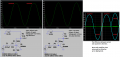
The input source in the test is as follows: DC Offset: 0V, Amplitude: 20mV, Frequency: 10Hz