Finding the equivalent resistance of a circuit!!

WBahn

Joined Mar 31, 2012
33,075
Yes, i forgot the "R7". Thank you!
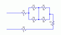
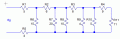
In this circuit i think that R2//R3, R4//R5 and R7, R8, R9 and R10 are in serie.
What do you think?
View attachment 221271
R10 has no effect. I think you meant R11 instead. This is "set up" stage of solving the problem and it is when all of the EE takes place, everything after this is math. If you get the set up wrong, then the math will likely not be able to catch it because, as far as the math is concerned, you are simply solving a different problem. So it pays to set up the problem and then carefully verify that your set up is correct before proceeding. You WILL make these kinds of mistakes throughout your career, what is valuable is to develop the habits, even rituals, that will allow you to catch them as a matter of routine.
 

WBahn

Joined Mar 31, 2012
33,075
If you are going to have multiple problems being discussed in the same thread (something we highly discourage for just this reason), then you have to be VERY clear in EVERY post exactly WHICH problem you are talking about. Otherwise nothing but chaos and confusion will reign.


Hi.
Sorry for taking so long to answer.
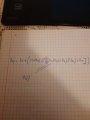
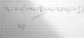
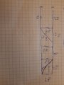
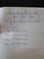
The 11 ohm exercise, i understood it by taking little steps, the whole equation looks a bit confuse but i think this is right:
View attachment 221340
So this equation says that ALL of the current MUST flow through both R1 and R7. Look at the original circuit. Does that make sense? I only see one resistor through which ALL of the current must flow.

I'll emphasize it again -- you need to get in the happen of looking at your work and asking if it makes sense. Mistakes often result in things that, even at a casual glance, are glaringly obvious that they are wrong. But you need to be looking to spot them.
 

Thread Starter

AntonioDuarte2001

Joined Nov 1, 2020
47
If you are going to have multiple problems being discussed in the same thread (something we highly discourage for just this reason), then you have to be VERY clear in EVERY post exactly WHICH problem you are talking about. Otherwise nothing but chaos and confusion will reign.


So this equation says that ALL of the current MUST flow through both R1 and R7. Look at the original circuit. Does that make sense? I only see one resistor through which ALL of the current must flow.

I'll emphasize it again -- you need to get in the happen of looking at your work and asking if it makes sense. Mistakes often result in things that, even at a casual glance, are glaringly obvious that they are wrong. But you need to be looking to spot them.
Sorry for the confusion i accidentally caused. I understood the error i made in that equation. Thank you for your responses. Slowly i think i am understanding much better this type of problems.
 

ericgibbs

Joined Jan 29, 2010
21,533
hi,
The equation of the 8d gave me the right result...
What was the result.??

I see that your answer for 8e gave 22Ω, is that the correct answer.?

If you don't post an original circuit of the problem that you are working on , which shows which resistor is which ie: R1 thru to R8
I cannot follow what you are doing.;)

E
8,e
 

Attachments

Last edited:

Thread Starter

AntonioDuarte2001

Joined Nov 1, 2020
47
hi,
The equation of the 8d gave me the right result...
What was the result.??

I see that your answer for 8e gave 22Ω, is that the correct answer.?

If you don't post an original circuit of the problem that you are working on , which shows which resistor is which ie: R1 thru to R8
I cannot follow what you are doing.;)

E
8,e
The result of the 8d equation is 11 ohm.
The exercise 8e gave me the correct result too, 54 ohm.
Trust me, i understood well these two circuits.
The 8f i dont. The equivalent resistance is 0. Why?
 

MrChips

Joined Oct 2, 2009
35,022
The result of the 8d equation is 11 ohm.
The exercise 8e gave me the correct result too, 54 ohm.
Trust me, i understood well these two circuits.
The 8f i dont. The equivalent resistance is 0. Why?
You are looking too hard.

Take a walk around the park (figuratively speaking). Stick to the paved path, don't walk on the grass.
Did you get mud on your shoes?

Electrons will stick to the path where there is least resistance. What path would the electrons take?
 

Thread Starter

AntonioDuarte2001

Joined Nov 1, 2020
47
You are looking too hard.

Take a walk around the park (figuratively speaking). Stick to the paved path, don't walk on the grass.
Did you get mud on your shoes?

Electrons will stick to the path where there is least resistance. What path would the electrons take?
The path without any resistance. Got it.
As for this circuit (exercise 8g), i think R1+R2. Then R12 + 3. Then R123 // R4. Then R1234 // R5. Then R12345 + R6. Then R123456 + (R7//R8)... im i going right?
Thanks.
 

Attachments

MrChips

Joined Oct 2, 2009
35,022
Stop and think again.

What defines two resistors in series?
What defines two resistors in parallel?

There is nothing that says you must begin with R1 and progress to R12.
You do it in any order that makes sense.
 

WBahn

Joined Mar 31, 2012
33,075
The path without any resistance. Got it.
As for this circuit (exercise 8g), i think R1+R2. Then R12 + 3. Then R123 // R4. Then R1234 // R5. Then R12345 + R6. Then R123456 + (R7//R8)... im i going right?
Thanks.
You keep completely ignoring what it means for two resistors to be in series and for two resistors to be in parallel.

If R1 and R2 are in series, which is what your R1+R2 requires, then any current that flows through R1 absolutely, without question, must, without doubt, flow through R2.

Do you see that this is not the case?

If so, then R1 and R2 are NOT in series and your very first step is wrong. No point going any further.
 

WBahn

Joined Mar 31, 2012
33,075
The path without any resistance. Got it.
As for this circuit (exercise 8g), i think R1+R2. Then R12 + 3. Then R123 // R4. Then R1234 // R5. Then R12345 + R6. Then R123456 + (R7//R8)... im i going right?
Thanks.
Take a step back and go with the basics -- you are making too many mistakes to be skipping steps. Stick to the fundamentals until you get things well enough under control that you can start skipping things and doing some of it in your head.

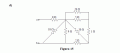
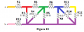
Fig18.png
Do you see any nodes that connect exactly two resistors? Is so, then those resistors are in series and can be combined and replaced by their series equivalent.

Do you see any pairs of resistors that each connect to the same two nodes? If so, then those resistors are in parallel and can be combined and replaced by their series equivalent.

Do that for the identified resistors and then redraw the circuit and the repeat this process again.

Also, this is a good time to put upper and lower bounds on the final answer.

Consider the following:

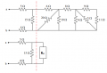
Fig18a.png

Rx represents the total resistance of everything to the right of the red line.

Do you see that the final resistance has a resistance that is equal to 9 Ω plus the parallel resistance of 15 Ω and Rx? We don't know what Rx is, but we know that it is more than zero and less than infinity. So using those two points we can immediately see that the lowest value the total resistance can have is 9 Ω (if Rx is 0 Ω) and the largest it can have is 24 Ω (if Rx is infinite).

Thus, by casual inspection, we know that any answer that is not between 9 Ω and 24 Ω is absolutely guaranteed to be wrong.

We can do this one better. Look at the mess that is Rx. Every path through it places an upper bound on the value of Rx, so look for the single path through that mess that goes through the smallest total resistance along that path. Hopefully you can see that it is 16 Ω (go in from the top node, through the 6 Ω, then the 10 Ω, and out the bottom node). So the biggest that Rx can be is 16 Ω. Rx could be a lot smaller than 16 Ω, but it is guaranteed that it will be no bigger. The largest value that the parallel combination of two resistors can have is the smaller of the two resistors (which in this case would be 15 Ω) and half of the larger (which in this case would be half of 16 Ω, or 8 Ω). So the largest that our total resistance can now be is 17 Ω.

Hence, with very little effort, we've narrowed out valid range of answers to between 9 Ω and 17 Ω. If we had to play the odds, we could just take the average and expect the that the answer will likely be somewhere in the 13 Ω range.
 

ericgibbs

Joined Jan 29, 2010
21,533
hi A,
Read your post understanding the previous problems, OK.

This is Circuit 8g, redrawn, it should enable you to build an equation and a value for Requiv.

Remember always try to redraw a circuit that appears complex to a simpler layout, before solving.

E
 

Attachments

Thread Starter

AntonioDuarte2001

Joined Nov 1, 2020
47
You keep completely ignoring what it means for two resistors to be in series and for two resistors to be in parallel.

If R1 and R2 are in series, which is what your R1+R2 requires, then any current that flows through R1 absolutely, without question, must, without doubt, flow through R2.

Do you see that this is not the case?

If so, then R1 and R2 are NOT in series and your very first step is wrong. No point going any further.
If R1 and R2 are not in series, then they are in parallel. But why? I used that trick ( i think it was you that mentioned it ) , of the index fingers, and it didnt work for R1 and R2, so i imediatly assumed that they were in series..
 

Thread Starter

AntonioDuarte2001

Joined Nov 1, 2020
47
hi A,
Read your post understanding the previous problems, OK.

This is Circuit 8g, redrawn, it should enable you to build an equation and a value for Requiv.

Remember always try to redraw a circuit that appears complex to a simpler layout, before solving.

E
hi A,
Read your post understanding the previous problems, OK.

This is Circuit 8g, redrawn, it should enable you to build an equation and a value for Requiv.

Remember always try to redraw a circuit that appears complex to a simpler layout, before solving.

E
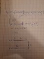
Using the denomination that you established, i procceded to simplifly the circuit.
Like this:
 

Attachments

Top