No need for another loop. You need one independent equation per mesh. The beauty of mesh current analysis is that by writing one loop equation for each mesh, in terms of the mesh currents, you are applying KVL around just the correct number of independent loops that are needed, and doing it in such a way that KCL is automatically satisfied.
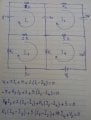
Now, having said that, you DO need to apply KVL around each mesh correctly. I'm assuming you are using conventional current and not so-called electron-flow current. Please correct me if I'm wrong. But, assuming conventional current, you need to decide if you are summing up voltage drops, or voltage gains, as you go around the loop. As you go through V1 in the direction of I1, you gain 4 V. But as you go through the 7 Ω resistor in the direction of I1, you LOSE the voltage across it.
Also, you seem to have three unknown resistances and two unknown voltage sources. That's five more unknowns and you need an additional equation for each of them. Additional loop equations won't help, because they will not be linearly independent to the four you already have.
What other information are you given?
You also should get in the habit of properly tracking your units. A voltage is not '4', it is '4 V', and a resistance is not '7', it is '7 Ω'. Track your units throughout your work, treating them like what they are, part of the quantities involved that multiply the numerical coefficients and apply the same rules of arithmetic that you do to the numbers. Most mistakes you make will mess up the units, allowing you to catch the mistake almost immediately. But that only works if the units are there and are being properly tracked from one step to the next.
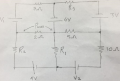
I need to determine the values of resistors (R1, R2, R3) and voltages (V1, V2) that result in the maximum power (Pmax) across the 2Ω resistor using a single-objective optimization algorithm in MATLAB. Therefore, I believe I should derive the power equation on the 2Ω resistor as a function of R1, R2, R3, V1, and V2.
I need to determine the values of resistors (R1, R2, R3) and voltages (V1, V2) that result in the maximum power (Pmax) across the 2Ω resistor using a single-objective optimization algorithm in MATLAB. Therefore, I believe I should derive the power equation on the 2Ω resistor as a function of R1, R2, R3, V1, and V2.
I think you are going down a rabbit hole. Whatever you pick for those component values, I can almost guarantee that I can pick different values that will increase the power in that resistor. Most likely, all I would need to do is just take whatever value you have for V1 and double it.
You know that the power in a resistor is in terms of the current flowing through it.
You know what the current flowing through it is in terms of your mesh currents.
Solve for those currents and plug them into the equation for the power in that equation, any you have your power equation in terms of those five unknowns.
And then you will almost certainly find that there is no single combination of them that results in maximum power in that resistor because the power will increase without bound as you change one or more of those unknown values.
I followed your suggestion by eliminating everything except the upper-left mesh and replacing the 2 Ω resistor and the 4 V source with short circuits. Additionally, I set V1 equal to 14 V. Through inspection, I found that I1 becomes +2. However, when I removed the 2 Ω resistor and the 4 V source in the mesh equation, I1 became -2. Therefore, I believe I should multiply voltage sources in the equations by a minus sign. Can it be inferred that in mesh current analysis, if we enter the minus part of a voltage source and exit from the positive part, we should use -V; otherwise, we should use +V?
I followed your suggestion by eliminating everything except the upper-left mesh and replacing the 2 Ω resistor and the 4 V source with short circuits. Additionally, I set V1 equal to 14 V. Through inspection, I found that I1 becomes +2. However, when I removed the 2 Ω resistor and the 4 V source in the mesh equation, I1 became -2. Therefore, I believe I should multiply voltage sources in the equations by a minus sign. Can it be inferred that in mesh current analysis, if we enter the minus part of a voltage source and exit from the positive part, we should use -V; otherwise, we should use +V?
the equations you wrote arent correct, you might wanna orient the polarity of each component then apply KVL correctly, also for maximum im not quite sure what you are looking for
I followed your suggestion by eliminating everything except the upper-left mesh and replacing the 2 Ω resistor and the 4 V source with short circuits. Additionally, I set V1 equal to 14 V. Through inspection, I found that I1 becomes +2. However, when I removed the 2 Ω resistor and the 4 V source in the mesh equation, I1 became -2. Therefore, I believe I should multiply voltage sources in the equations by a minus sign. Can it be inferred that in mesh current analysis, if we enter the minus part of a voltage source and exit from the positive part, we should use -V; otherwise, we should use +V?
You just need to consider whether the voltage increases or decreases as you go through the component in the direction of your mesh current.
Remember, your mesh equation is nothing more than KVL applied around the mesh. You can decide whether you want to sum up the voltage gains, or sum up the voltage drops. Totally arbitrary. But once you decide, you need to be consistent for each mesh.
So, looking at the original circuit and that upper-left mesh, let's sum up the voltage drops (which is typically what people do).
As you go from the negative terminal of a voltage source to the positive terminal, you GAIN whatever the output voltage is, which means that the voltage DROP is the negative of that. So the voltage drop across the source is -V1.
As you go across a resistor in the direction of the current, you DROP a voltage that is equal to the current times the resistance. So the voltage drop across the 7 Ω resistor is (I1)(7 Ω).
Similarly, the voltage drop across the 4 V source is -4 V, because you are actually gaining voltage.
The 2 Ω resistor has two currents superimposed on it. I1 drops a voltage while I2 gains voltage, so that drop is (I1-I3)(2 Ω).
The resulting equation is therefore:
-V1 + I1(7 Ω) - 4 V + (I1-I3)(2 Ω) = 0
If you had chosen to sum up the voltage gains, the only difference is that each term in this equation would be multiplied by -1.
 Facebook
 Google
 GitHub
 Linkedin
 430.8 KB Views: 27