Find the voltage gain

Thread Starter

ADCapacitor

Joined Feb 3, 2016
42
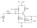
β=210, Vt=26mV, Vbe(on)=0.7V
How to find Vs,
then find the Voltage gain Vo/Vs ?
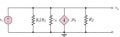
I try to draw the small signal model to solve the problem


Vth=15*R2/[R1+R2]
Vth=1.62V

Rth=R1//R2
=5.5kΩ

-Vth+Rth*Ib+Ie*Re+Vbe=0
Vth=Rth*Ib*(1+β)*Re
Ib=(Vth-Vbe)/Rth+Re(1+β)
=8.2μA

Since
Re is short in Ac

Rπ=Vt/Ib
=3.18k ohm

Vo=-β*ib*Rc
How to find Vs,
then I can get Vo/Vs ?
 

Attachments

shteii01

Joined Feb 19, 2010
4,644
Why Vo is at emitter ??
Current amplifier?

The better question is how resistor has a value of 10 uF. On the other hand that same resistor is behind dc blocking capacitor so it likely does not matter.

Ok. Question to OP. What text are you using for learning these stuff?
My textbook has some good examples on these things and explanations for the approximations that can be used to shortcut thought the complicated math.
 

shteii01

Joined Feb 19, 2010
4,644
With current amplifier or buffer I think it is better not to include the collector resistor.
You are most likely right. I assume that we are dealing with textbook exercise, therefore the actual exact function of the circuit does not matter.
 

Thread Starter

ADCapacitor

Joined Feb 3, 2016
42
Thank you
I make some mistakes when redrawing the circuit diagram
The resistor with wrong label is the internal resistor of the signal generator.And the value is not given.
I think this one is better
 

Thread Starter

ADCapacitor

Joined Feb 3, 2016
42
Current amplifier?

The better question is how resistor has a value of 10 uF. On the other hand that same resistor is behind dc blocking capacitor so it likely does not matter.

Ok. Question to OP. What text are you using for learning these stuff?
My textbook has some good examples on these things and explanations for the approximations that can be used to shortcut thought the complicated math.
I am using the lecture notes for learning these stuff.
My teacher give us this question for practice
Which textbook are you using?It sounds good
 

WBahn

Joined Mar 31, 2012
29,930
With current amplifier or buffer I think it is better not to include the collector resistor.
I'm not at all sure that this is supposed to be a current amplifier. Even if it is, the collector resistor could be there to either put a limit on the current output or to reduce the collector-emitter voltage to something that compensates for the Early effect.
 

Jony130

Joined Feb 17, 2009
5,487
So you have a traditional Common Emitter amplifier. And your problem is Vs ?? So first try to draw the "correct" small-signal model.
An then you will see that if internal resistor of the signal generator Rs = 0Ω Vin = Vs = voltage across rpi.
 

Thread Starter

ADCapacitor

Joined Feb 3, 2016
42
thank you
I have some further questions
I found that some examples use this "RTH=0.1(1+β)Re" to find the Rth
And it sometimes use Rth=R1//R2
But why?
 

Jony130

Joined Feb 17, 2009
5,487
When we want to find the DC operation point (quiescent current) in order to simplify the calculation we use thevenin's theorem and replace Vcc and voltage divider at the base by his thevenin equivalent. And in this case Rth = R1/R2 and Vth = R2/(R1+R2)
http://forum.allaboutcircuits.com/threads/transistor-base.81886/#post-585781
I found that some examples use this "RTH=0.1(1+β)Re" to find the Rth
Can you show us the example? Because (1+β)Re is a AC resistance seen from the base terminal when we looking into emitter and if we ignore r'e.
 

Thread Starter

ADCapacitor

Joined Feb 3, 2016
42
Design a bias-stable circuit . Let β = 100 and VBE(on) = 0.7 Vm , Ic=0.7mA, Vce=4V

this example use Rth=0.1(1+β)Re to find Rth
Is "Bias-stable" imply that we can use Rth=0.1(1+β)Re to find the Rth?
 

Jony130

Joined Feb 17, 2009
5,487
OK I see. This formula "Rth=0.1(1+β)Re" is a rule of thumb used sometimes by a designer. And this rule means that we must choose R1||R2 < 0.1(1+β)Re for "bias-stable". This rule ensure that our voltage divider voltage is "stiff". Because base current is a load for our voltage divider. And to ensure that our divider voltage do not change much after we loading it we use this "rule of thumb" to select R1 and R2. The slightly different rule of thumb is to choose voltage divider current Id = Vcc/(R1+R2) at least 10 times the base current. So we have:
R1 = (Vcc - Vb)/(11*Ib)
R2 = Vb/(10*Ib)
 
Top