Find Efficiency of a Buck Converter

Thread Starter

Jimmy Mejia

Joined Oct 13, 2019
6
Hi,
I am just doing some reading on power electronics and I came across this question. They state the answer, which is 0.55. What I can't figure out is how they got the answer. The questions is:
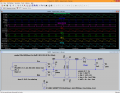
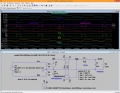
"A dc-dc converter has an input voltage of Vg=5V, and it supplies a computer processor with V=0.5V at 50A (25 W). The converter is a buck converter, and it uses a diode having a forward voltage drop of 0.5V. All losses other than the diode conduction loss are negligible. Estimate the efficiency of this converter"
Efficiency is given by PowerOut/PowerIn. The Power out is 25W, information is given. I apologize if this seems vague but this is essentially all the information I have. I am assuming the Diode is acting like a parallel switch to the output and a MOSFET in series with the voltage source Vg. If someone can help me understand the process of getting the answer. I did a quick search on here but with no luck. Thank you in advance.
 

Papabravo

Joined Feb 24, 2006
21,225
First calculate the duty cycle for continuous operation, assuming the inductor current never drops to 0.

\(D\;=\;\frac{V_o}{V_i}\;=\;\frac{0.5}{5}\;=\;0.1\)

Beats me. Each time I think I have the answer, there is a problem.
 
Last edited:

ronsimpson

Joined Oct 7, 2019
3,037
Input voltage is 5V and output is 0.5V at 50A. That is strange but OK. Because the voltage is going from 5 to 0.5 the supply is a "buck" type.
When the switch is on current flows through the switch, inductor to the load.
When the switch is off current flows through the diode, inductor to the load.


The switch will be on a small percent of the time while the diode will be conduction a large percent of the time.
-----not quite true but just to test a thought-----
Pretend the diode is conducting 100% of the time. (more like 80%) For the diode you have 0.5V across the diode and 50A = 25 watts. Because the diode is off part of the time the power loss will be a little smaller than 25W. I do not see how "0.55W" can be close to right.
-----back to reality----
The equations in post #3 assumes the diode and switch voltage & power loss are zero. In this example we are told the switch loss is too small to count. But the diode loss (quote RonSimpson) is very large and eats up about 1/2 of all the power. To be very picky, the output is not just the 0.5V output but for the formula it should be Vout + DiodeDrop = 0.5+0.5=1.0V. I think the duty cycle formula needs to have the diode loss included.

My big question: Why do I get about 50x more power loss than the teacher?
 

ronsimpson

Joined Oct 7, 2019
3,037
capacitor power when the switch is off.
No. When the switch is closed, energy is stored on the inductor and the capacitor. When the switch is open energy is moved from the inductor and capacitor to the load. So really the cap is not the main storage device. (again: current flows all the time in the inductor)

Example: the inductor current might go from 40 to 60A when the switch is closed and from 60 to 40 when the switch is open. An average of 50A flows into the load & capacitor. Inductor current above 50A goes into the cap, and when the inductor current is below 50A some current is pulled from the cap.
 

Papabravo

Joined Feb 24, 2006
21,225
No. When the switch is closed, energy is stored on the inductor and the capacitor. When the switch is open energy is moved from the inductor and capacitor to the load. So really the cap is not the main storage device. (again: current flows all the time in the inductor)

Example: the inductor current might go from 40 to 60A when the switch is closed and from 60 to 40 when the switch is open. An average of 50A flows into the load & capacitor. Inductor current above 50A goes into the cap, and when the inductor current is below 50A some current is pulled from the cap.
I understand that the current rises and falls as the switch is opened and closed. What is less obvious is the magnitude and the timing of those excursions. We know from the voltage in and out ratio that the nominal duty cycle is going to be 10% and that some mechanism for adjusting the duty cycle exists as the voltage rises and falls. Still, to get the efficiency we need to estimate the input power consumption, and I'm missing the approach to get that estimate.
 

panic mode

Joined Oct 10, 2011
2,749
Wiki shows Buck Converter in reasonable detail, including diode Pd which in this case is
Pd=Vd*(1-D)*Io=22.5W
And since this is the only loss, efficiency is

Po/(Po+Pd)=25/(25+22.5)=52.6%
 

BobTPH

Joined Jun 5, 2013
8,961
When the diode is conducting the power loss is 50%. It is conducting 90% of the time. Hence the average power loss is 0.9 x 50% = 45%. Hence the efficiency is 100 - 45 = 55%.

Bob
 

ci139

Joined Jul 11, 2016
1,898
most simple buck converters reach efficiencies 71% to 86% and that at some output power range

55% is apx. that of the linear regulator (which is usually more robust and "quiet") there's no default reason to go on with such design

efficiency = P.load/P.in (if not otherwise defined)
  • P.load = 25W
  • V.out = 0.5V
  • V.out.series = V.D.flyback = 0.5V
  • I.out =50A
  • useful output power = IU = I·V.out = 50·0.5 = 25W
  • total output power = IU = I·(V.out + V.out.series) = 50·(0.5 + 0.5) = 50W
  • incase of neglible losses the least is and the input power
  • thus P.inp=50W
  • V.in=5V -- might be actually whatever
  • efficiency 25W / 50W = 50% (assuming 5 to 1 V pulse transformer)
but if you have a different topology the result may vary by such -- as now a part of power is supplied to OUTP "in series"
the ramp up slope depends on V.in - V.out + the ramp down slope depends on I.out ← what you need to find for ideal v. of it is
_–¯|¯–_ _–¯|¯–_ _–¯|¯–_ Lim efficiency @ t.ramp.u/d) → t.optimal where the most power is supplied

the formulas involved are
  • def. : I₀ = 50A , R₀ = .5V/50A = 10mΩ
  • ramp-up current :
    I = I₀ · (1 – exp( – R₀ / L · t) ) ← but this may vary around 50A → thus instead of
    50A and t we may need to use ... say 100A and t + Const.
  • ramp-down current :
    I = I₀ · exp( – R₀ / L · t ) ← but this "includes" the voltage drop on the fly-back diode → thus instead of
    R₀ we now have R₀ = (0.5 + 0.5)·1V/50A = 20mΩ and as with prev.
    we may need to adjust I₀ to be a bit greater than 50A (that is average outp.) and thus correct the R₀ the second time
    • the initial voltage the inductor sees V = 5V - 0.5V = 4.5V
    • the initial charge-up series-resistance on the power path is Ri
    • the secondary dis-charge ser.-resistance on the power path is 2·Ri ( /!\ at this particular case !!! )
  • etc.
the Lim here assumes slight "waving" around the average outp
__________________________

so we must find I.ramp slope around 50A ← as it's average we assume that 100A for max
(we can't assume ∞ coz it'd instantly load the inductor with very high NRG !!)

what we want to know is (dI / dt) at I = I₀ / 2 (50A !)
so our charge-up R is 5mΩ L is L we want to get t at I₀ · (1 – exp( – R₀ / L · t) ) = I₀ / 2
e.g. where (1 / 2) = exp( – R₀ / L · t) → ln 2 = R₀ / L · t → t = (L / R₀) · ln 2
di / dt = I₀ · ( 0 – exp( – R₀ / L · t) ) · ( – R₀ / L ) = I₀ · R₀ / L · exp( – R₀ / L · t)
replacing the t with (L / R₀) · ln 2 we get ...
Lim ∆t→0 , ∆i / ∆t = I₀ · R₀ / L · exp( – R₀ / L · (L / R₀) · ln 2 ) = I₀ · R₀ / L / 2

or more clear chargeup : ∆I / ∆t = (I₀ · R₀) / (2 · L) where I₀ · R₀ = 0.5V thus

∆I / ∆t = E(U.load) / (2 · L)
__________________________

for discharge . . . we also assume we start from 100A ! . . . (↑ to match the prev. ↑)
but here R₈ = 2 · R₀.prev = 10mΩ . . . what we want to know is (dI / dt) at I = I₀ / 2 (50A ! ←↑ the peak current stays)
e.g. where (1 / 2) = exp( – R₈ / L · t ) → ln 2 = R₈ / L · t → t = (L / R₈) · ln 2
di / dt = I₀ · exp( – R₈ / L · t ) · ( – R₈ / L) = I₀ · exp( – R₈ / L · (L / R₈) · ln 2 ) · ( – R₈ / L) = ( I₀ ( – R₈) / L ) / 2 = – U.outp.tot / (2 · L) = ∆I / ∆t
where U.outp.tot = 1V . . . so

dis-charge ~ ∆I / ∆t = 2 · E(U.load) / (2 · L)
charge-up ~ ∆I / ∆t = E(U.load) / (2 · L) ~ 2 × as fast as discharge at high frequency and sufficient ballast capacitors at both sides !!!
so

Budget load (τ/3 · 50A · 2 · 0.5V + 2·τ/3 · 50A · 1 · 0.5V) / (τ/3 + 2·τ/3)
Budget input (τ/3 · 50A · 2 · 5V + 2·τ/3 · 0A · 1 · <undefined>V) / (τ/3 + 2·τ/3)

Efficiency = P.load / P.out · 100% = (τ/3 · 2 · 0.5V + 2·τ/3 · 0.5V) / (τ/3 · 2 · 5V) = (1 / 10) · 2 = 20%
 
Last edited:

Alec_t

Joined Sep 17, 2013
14,313
Here's my take:
Since the diode is in series with the load the average current must be the same in both. We know the voltages across each are the same. Therefore, the average power in each is the same so the efficiency is 50%.
 

Alec_t

Joined Sep 17, 2013
14,313
.... which is why I referred to average current. Whether the load draws instant current from a reservoir cap or directly via the diode, in the long term all the energy reaching the load has to come via the diode.
 

crutschow

Joined Mar 14, 2008
34,432
in the long term all the energy reaching the load has to come via the diode.
Not all of it.
What the switch is on (diode off) the output current is being supplied by the input source.
Thus the diode carries the average current for (1- duty-cycle) of the time.
 

ci139

Joined Jul 11, 2016
1,898
i estimated something incorrect ?? it still going along the current (only) budget (e.g. 55%) -- which i don't like
because it does not define efficiency normally . . . ( ← at least according to LTSpice -- which is NOT . . . any definitive reference)
. . . the duty being 1:6 ?? output/(input+outp) or (load/input·input/(input-output))*const.RMSin2pkA
. . . it's likely the 1-st ... ... ... but it must agree with Ro , Io "=" if we fix outp to
10mΩ 5/10m:1/10m the 1st- loads 10% (of input power ? U²/R ? 1%) to load -- thus Budget
so half of 90%(99%) goes by next 45%(49.5%)+10%(1%) =55%(50.5%) -- ? U²/R ? does not work out here
. . . unless it's I = Const , U changes ← is the current-linear 10% option ((but i quite can't formulate it ?))
↓↓ there might be some integration err. involved ... + some switching(-time) losses ↓↓
_________________
restart :: charge 5V/10mΩ=500A , dis-charge 1V/10mΩ=100A // ← the 10mΩ never sees that 1V as Diode eats half off that
// -- the only way for D to drop 0.5V at 50A would be having series resistance of 10mΩ . . . avg. 50A makes it Const. ... or forward (with respect to current) voltage that would subtract off from induced voltage
dis-charge 1V/20mΩ=50A ~versus~ 1V/10mΩ=100A
50A=500A(1-e^(-t·R/L)) , 50A=50A·e^(-t·2·R/L) // ← there is no data to form the
discharge formula
or 50A=100A·e^(-t·R/L)
t.ch = L/R·ln(10/9) , t.dh = L/R·ln 1 (( ← ln 1 = 0 → t.dh = 0 )) or t.dh = L/R·ln 2
charge di₁ / dt = 500A·R/((10/9)·L) , discharge di₀ / dt = 50A·2·R/L // ← the least is without context
or discharge di₀ / dt = 100A·R/(2·L)
so di₁ / di₀ = (zeros off) 45/10 = 4.5 <> 6 . . .
or di₁ / di₀ = (zeros off) 45/5 = 9 <> 6 ...
// -- only way is to define |±∆i| > 0 and balance up from there ?
or accept the fact that the truth is in between 9 and 4.5 - taking random avg. 2·9·4.5/(9+4.5) = 6 ( i n s a n e )
 

Attachments

Last edited:

Alec_t

Joined Sep 17, 2013
14,313
Thus the diode carries the average current for (1- duty-cycle) of the time.
I agree it carries current for that time, but not the average current. I think it will pass above-average current in that period, since the current will be topping up the cap charge as well as flowing through the load.
I tried a quick sim to see what LTS came up with, but had problems convincing LTS of the non-realistic nature of the load and diode, e.g. setting Vfwd=0.5V as a diode parameter didn't get the 0.5V diode drop I expected.
 
Top