Facebook
 Google
 GitHub
 Linkedin
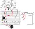
One of the main problems you will have with any 3D printer that uses spools is when the spools get tangled and refused to feed or just flat run out of filament. I have come up with an alarm that will notify you if either condition occurs hopefully in time to fix the problem. Because I have one hand and I am stuck in a wheelchair the spool reel is facing the wrong way on my printer. So I came up with a kludge that would help me use the run backwards installed spool and feed the printer reliably. This shows my modified feed assembly:

The sensors I am about to show can be used on any 3D printer.
The tangle sensor
I used a 2 x 4 cut to 1 foot ,The first project was the tangle sensor which was the easiest to do. I took an alarm switch which is a modified reed switch, and super glued a small square of steel on one end. I used the large pulley design I made for the end of the board and attached a mount for a 5/8” x 1/4” neodymium magnet which I assembled with super glue (I use super glue a lot when I 3D print). When the tangle sensor magnet is attached to the reed switch it is closed. So I made this circuit on a protoboard to notify me when the condition has occurred and perhaps get there in time to save the print:

I used a CMOS 555 to limit the current which seemed to work well. It did indeed allow me to intervene in with enough time to save several prints .
A quick note about hardware my standard screw size is #6/32 x2”, I buy them in packs of 100,And cut them down with this tool as I need shorter lengths:

I make my pulleys in two parts they interlock together and use super glue to keep them that way. After you print all of the parts you should have two large pulleys with matching bases (one of them is the sensor base for the tangle sensor), 2 small idler pulleys and matching bases. and the OoF (I'll cover that later).
When I know I am going to screw a #6/32 into a piece of plastic I make the hole in the print design approximately as close to tap size as I can. A tap is not needed since hard metal trumps soft plastic .
I will assume the user will cut the screws to the proper length they need to do the job. I have revised this design enough that the 2 x 4 is looking like Swiss cheese. I used #6 wood screws to mount the various items on the board.
Anyhow, the tangle pulley and magnet when you are finished should look a lot like this:

The pulley protector Is to protect the idler pulley on the far end of the board:

At this point the tangle sensor is complete. While the electronics is not in the picture the first picture shows the final set up of the sensor.
OoF (Out of Filament) Sensor
I wasted a lot of plastic trying to do this with a magnet. Finally I gave up and tried a new approach. I am a major fan of KISS (keep it simple stupid) and decided to go with a contactor solution instead. I used qty 2 5/16” x 5/16” neodymium magnets. A drop of super glue will ensure they stay inside the holes printed into the sensor bodies, they should both be flush when inserted as shown.

Be sure they are attracted to each other when inserted, This picture is of an earlier build Hold off putting the top magnet in until everything is glued together:

as they are a right PITA when the screws keep trying to be attracted to them. After the glue dries on the bottom shell then glue the top magnet into the top shell.I found it much easier to put the magnet on a metal surface, put a drop of super glue on top of the magnet, then slide the shell over the magnet as deep as it can go. After everything dries screw in the bottom contact screw the head should fit in the recessed area on the bottom shell (screw length should be no longer than ¾”), when adding the nut on this screw I found I had to glue the head down inside the shell so I could get the nut on as shown. Be sure not to get any super glue on the top of the head as this is a contact point for the sensor, if you happen to get some on the threads that would be OK since you're not going to remove this screw again. You can always do this later but I added a short piece of wire as a contact point for later connection:


Next assemble the OoF bottom pulley And check to see that they mesh as shown. You may need to sand the top pulley smooth. I did this by using a long screw and a drill motor you can see the sand marks in the picture. The screws should be no longer than ¼”, since that is the depth allowed in each of the two OoF top and bottom pieces. I would use a drop of super glue to hold the screw in place. As you can see the top pulley is going to need some rework on the screw length. Under ¼” is acceptable but I would not accept longer. Do not tighten the screws, as each pulley should rotate freely on this screw. Super glue the nuts into place.

The sensors I am about to show can be used on any 3D printer.
The tangle sensor
I used a 2 x 4 cut to 1 foot ,The first project was the tangle sensor which was the easiest to do. I took an alarm switch which is a modified reed switch, and super glued a small square of steel on one end. I used the large pulley design I made for the end of the board and attached a mount for a 5/8” x 1/4” neodymium magnet which I assembled with super glue (I use super glue a lot when I 3D print). When the tangle sensor magnet is attached to the reed switch it is closed. So I made this circuit on a protoboard to notify me when the condition has occurred and perhaps get there in time to save the print:
I used a CMOS 555 to limit the current which seemed to work well. It did indeed allow me to intervene in with enough time to save several prints .
A quick note about hardware my standard screw size is #6/32 x2”, I buy them in packs of 100,And cut them down with this tool as I need shorter lengths:
I make my pulleys in two parts they interlock together and use super glue to keep them that way. After you print all of the parts you should have two large pulleys with matching bases (one of them is the sensor base for the tangle sensor), 2 small idler pulleys and matching bases. and the OoF (I'll cover that later).
When I know I am going to screw a #6/32 into a piece of plastic I make the hole in the print design approximately as close to tap size as I can. A tap is not needed since hard metal trumps soft plastic .
I will assume the user will cut the screws to the proper length they need to do the job. I have revised this design enough that the 2 x 4 is looking like Swiss cheese. I used #6 wood screws to mount the various items on the board.
Anyhow, the tangle pulley and magnet when you are finished should look a lot like this:
The pulley protector Is to protect the idler pulley on the far end of the board:
At this point the tangle sensor is complete. While the electronics is not in the picture the first picture shows the final set up of the sensor.
OoF (Out of Filament) Sensor
I wasted a lot of plastic trying to do this with a magnet. Finally I gave up and tried a new approach. I am a major fan of KISS (keep it simple stupid) and decided to go with a contactor solution instead. I used qty 2 5/16” x 5/16” neodymium magnets. A drop of super glue will ensure they stay inside the holes printed into the sensor bodies, they should both be flush when inserted as shown.
Be sure they are attracted to each other when inserted, This picture is of an earlier build Hold off putting the top magnet in until everything is glued together:
as they are a right PITA when the screws keep trying to be attracted to them. After the glue dries on the bottom shell then glue the top magnet into the top shell.I found it much easier to put the magnet on a metal surface, put a drop of super glue on top of the magnet, then slide the shell over the magnet as deep as it can go. After everything dries screw in the bottom contact screw the head should fit in the recessed area on the bottom shell (screw length should be no longer than ¾”), when adding the nut on this screw I found I had to glue the head down inside the shell so I could get the nut on as shown. Be sure not to get any super glue on the top of the head as this is a contact point for the sensor, if you happen to get some on the threads that would be OK since you're not going to remove this screw again. You can always do this later but I added a short piece of wire as a contact point for later connection:
Next assemble the OoF bottom pulley And check to see that they mesh as shown. You may need to sand the top pulley smooth. I did this by using a long screw and a drill motor you can see the sand marks in the picture. The screws should be no longer than ¼”, since that is the depth allowed in each of the two OoF top and bottom pieces. I would use a drop of super glue to hold the screw in place. As you can see the top pulley is going to need some rework on the screw length. Under ¼” is acceptable but I would not accept longer. Do not tighten the screws, as each pulley should rotate freely on this screw. Super glue the nuts into place.
Last edited: