Figuring out a circuit

Thread Starter

Assemblymen

Joined Dec 12, 2018
20
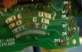
If you know how to read resistor values, can you tell us what the ones on the right hand in the second photo are?
If you don't know how to read them and they are marked with colored bands, would you post a photo clear enough to allow reading them? I can't tell because of the movement during making of the existing photo.
I can probably get a even better picture of them. With different lighting it will be viewable better. Give me some time. It would be better if someone from the DC metro area could come and see the whole situation.
 

BR-549

Joined Sep 22, 2013
4,928
Sounds like it should be easy doesn't it? Can you get any technical paperwork on the controller?

Can you get any technical paperwork on new controllers?

One has to research what parameters and methods are used in the existing controller.......then mate it to the parameters and method of the new controllers.

It might be a lot easier to purchase the proper controller needed.

Many product manufacturers will not share technical information.
 
Last edited:

absf

Joined Dec 29, 2010
1,968
This is quite similar to the 4 bit binary switches used in Yamaha FE-series electone organs as Rhythm Balance and Rhythm Volume Control . They looks like a normal volume control but larger. The rhythm balance conntrol is in sliding form.

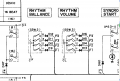
Here's the schmatics of them in FE-60...
The controls are connected to the main chip which was named KAS (Key assigner system) and I think it was a 64 pin DIP chips. All the keys from the keyboard are also connected to this chip.

Yamaha digital Pot.PNG

I couldn't find any more of them left so I cannot show them here.

Allen
 
Last edited:

absf

Joined Dec 29, 2010
1,968
consider the common line is the 4th curve line from the top is connected to 0V. And the uppermost curve is the MSB of the 3 bit binary switch.

Turning the wiper from left to right would change the bin code from
000->010->100->010->111->111->111->100->110->011->000->000
digital pot 2B_200810_01.jpg
So I think it is possible to use a MCU with ADC and connect a linear potential meter to it. Then write a program to read the analog input from the pot and convert it to binary numbers in 12 steps. You have to be familiar with one type of mcu and be fluent in one type of programming language to do this project.

Allen
 

Thread Starter

Assemblymen

Joined Dec 12, 2018
20
Sounds like it should be easy doesn't it? Can you get any technical paperwork on the controller?

Can you get any technical paperwork on new controllers?

One has to research what parameters and methods are used in the existing controller.......then mate it to the parameters and method of the new controllers.

It might be a lot easier to purchase the proper controller needed.

Many product manufacturers will not share technical information.
You say it would be easier, except I own over 100 RC cars with the very same controllers, and am trying to make a buisness where by people can drive a 28th scale car on the race track, and other types, that are hooked up to steering wheels, cameras, pedals, and can be see with a TV or for headset. A virtual type experience, except it's more real.
 

BR-549

Joined Sep 22, 2013
4,928
I am not competent with VR, R/C or even game controllers. Never played computer games.

If you can not get adequate documentation......a tech will need to measure and reverse engineer it.

Apparently, the controller has a digital processor. That means either a digital input or a scaled analog input.

What type of signal does the new controllers provide? Whatever it is......it will need to be scaled for the processor.

So first verify the existing controller "language"........then author a new "translation" for the new controller.

The new controller must pattern the old.


Edit: One more suggestion. Don't open a business with mickey mouse tech. And the public, especially the young, love to hammer and shower the environment.
 
Last edited:

Thread Starter

Assemblymen

Joined Dec 12, 2018
20
I am not competent with VR, R/C or even game controllers. Never played computer games.

If you can not get adequate documentation......a tech will need to measure and reverse engineer it.

Apparently, the controller has a digital processor. That means either a digital input or a scaled analog input.

What type of signal does the new controllers provide? Whatever it is......it will need to be scaled for the processor.

So first verify the existing controller "language"........then author a new "translation" for the new controller.

The new controller must pattern the old.


Edit: One more suggestion. Don't open a business with mickey mouse tech. And the public, especially the young, love to hammer and shower the environment.
The steering wheels and both pedals all have potentiometers that can be used to replace the potentiometers in a regular radio control there's a video on YouTube where a guy does it I'm just trying to do the same thing with the controllers that I had if I can't do it with the controllers I have that I have to invest in a whole lot more cars when I already have a hundred the processing that's in the actual gaming controller gets thrown away and the only thing that gets used is the potentiometers

I'm just trying to replace the circuit board in the pictures both of them with potentiometers to move the cars
 
Last edited by a moderator:

BR-549

Joined Sep 22, 2013
4,928
I wouldn't know. Haven't seen video. That board that you posted, appears to be a digital encoder, not a potentiometer.

It sorta looks like a slider......but it is outputting a voltage pattern, not a voltage amplitude.
 

Thread Starter

Assemblymen

Joined Dec 12, 2018
20
I wouldn't know. Haven't seen video. That board that you posted, appears to be a digital encoder, not a potentiometer.

It sorta looks like a slider......but it is outputting a voltage pattern, not a voltage amplitude.
I know it's not a potentiometer I want to know if I can put a potentiometer in the place of the one side which is the steering and the other side the one with the bigger break in the middle is the brake pedal and gas pedal so I want to know if I can put two potentiometers one for the gas and one for the brake in place of that side of the board it is staring potentiometer in place of the one with the smaller break

It would help if you ran the whole thread and not just parts of it because I had explained exactly what I'm looking to try to do in the whole thread

I don't really care what it is the question is can a potentiometer replace what it does

In a regular hobby grade radio control potentiometers exist and a game controller steering wheel and pedals can replace the functions with some wiring switching, my question is can I replace the two boards it's a single board with stuff on both sides with potentiometers the functions are the same steer left steer right gas forward brake & reverse
 
Last edited by a moderator:

Thread Starter

Assemblymen

Joined Dec 12, 2018
20
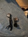
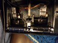
The two piece is sitting together all the throttle and steeringThe t it connects all the circuits with one swipe, the other two pictures all of the potentiometers with the steering wheel on the pedal and brake in a gaming steering wheel set, the circuit boards that are in the gaming steering wheels it throw it out and the potentiometers are the only thing used
 

Attachments

Top