Figuring out a circuit

Thread Starter

Assemblymen

Joined Dec 12, 2018
20
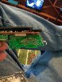
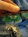
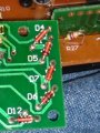
I'm looking for somebody in the DC metro area that can help me figure out a circuit, I need to make some connections, and I need to know if it's possible somebody in this area please respond and I'll make it worth your while because I need to get the circuits completed.
 

Thread Starter

Assemblymen

Joined Dec 12, 2018
20
Give us all the details and maybe someone can help you long distance.
I want to attach a gaming steering wheel and pedals in place of these 2 circuits. These are the steering and gas and brake of an rc radio control. I want to be able to control the car with a steering wheel and pedals set.
 

Thread Starter

Assemblymen

Joined Dec 12, 2018
20
Give us all the details and maybe someone can help you long distance.
I built this, and I want to make driving drones so people can race on it. It folds up and fits in a trailer. It's 25 feet long 8 feet wide, and the turns are banked at 30 degrees.
image000000_02.jpg
 

Thread Starter

Assemblymen

Joined Dec 12, 2018
20
The short answer to your question is no. The controllers are more complex than just simple potentiometers.
I do know that regular radio control can be done with potentiometers because they have potentiometers in them the biggest question is are these circuits like potentiometers those four lines are all connected by one wiper on both sides the throttle and steering the biggest is that can the four circuits for the forward and reverse side which is the one with the Gap in the middle be controlled by two potentiometers
 

Thread Starter

Assemblymen

Joined Dec 12, 2018
20
The short answer to your question is no. The controllers are more complex than just simple potentiometers.
There are four wires that go through the board from the break and gas side so my question is shouldn't 2 potentiometers be able to control that.
 

Thread Starter

Assemblymen

Joined Dec 12, 2018
20
The short answer to your question is no. The controllers are more complex than just simple potentiometers.
The circuits themselves don't look that complicated they just have a bunch of resistors on them all at all I'm just wanting to make sure whether it can be done or not which is why I need somebody in the local area to actually look at them. It's a very very simple board on each side. Only 8 wire connections go through there should be some way. At the bare minimum I would need like I said the gas and brake side to be controllable by potentiometers.I can come up with another way for the steering to be controlled.
 

ebp

Joined Feb 8, 2018
2,332
Some closer photos of the boards and some photos of the opposite sides might be helpful.

The arrangement of contacts suggests "Gray code" to me - the output is actually digital and the arrangement is such that there is just a single bit that changes from one position to the next (done to prevent errors). However, the more complex one seems to have more positions than can be encoded by the number of bits it would take (3 bits can only encode 8 positions and it looks like there is one common "bar" and 3 sets of small contacts).

It would certainly be possible to use a microcontroller to encode the output of potentiometers and somehow emulate the contacts on the switches, but it might be rather complex depending very much on what the switches actually do. Of course this also requires custom programming.
 

Thread Starter

Assemblymen

Joined Dec 12, 2018
20
Some closer photos of the boards and some photos of the opposite sides might be helpful.

The arrangement of contacts suggests "Gray code" to me - the output is actually digital and the arrangement is such that there is just a single bit that changes from one position to the next (done to prevent errors). However, the more complex one seems to have more positions than can be encoded by the number of bits it would take (3 bits can only encode 8 positions and it looks like there is one common "bar" and 3 sets of small contacts).

It would certainly be possible to use a microcontroller to encode the output of potentiometers and somehow emulate the contacts on the switches, but it might be rather complex depending very much on what the switches actually do. Of course this also requires custom programming.
Just so you know there are two photos included one of each side of the board
 

Thread Starter

Assemblymen

Joined Dec 12, 2018
20
Some closer photos of the boards and some photos of the opposite sides might be helpful.

The arrangement of contacts suggests "Gray code" to me - the output is actually digital and the arrangement is such that there is just a single bit that changes from one position to the next (done to prevent errors). However, the more complex one seems to have more positions than can be encoded by the number of bits it would take (3 bits can only encode 8 positions and it looks like there is one common "bar" and 3 sets of small contacts).

It would certainly be possible to use a microcontroller to encode the output of potentiometers and somehow emulate the contacts on the switches, but it might be rather complex depending very much on what the switches actually do. Of course this also requires custom programming.
The gaming steering wheel and foot pedals are controlled by three potentiometers one that steers and one each for the gas and brake my question is can each of those potentiometers replace what is all in the single board one side is for steering and yes you're correct the wipers that go with it contact all four at one time and allow the connections to be made there's no microchips on the board itself it all saiyans signals from each of the lines through eight little wires that you can see in the pictures
 

wayneh

Joined Sep 9, 2010
18,097
Huh, could this thing be as simple as the old telephone keypad, where various combinations provided different resistance values?

But anyway, those rotating parts are not called potentiometers, they're rotary digital encoders.
 

Thread Starter

Assemblymen

Joined Dec 12, 2018
20
Huh, could this thing be as simple as the old telephone keypad, where various combinations provided different resistance values?

But anyway, those rotating parts are not called potentiometers, they're rotary digital encoders.
Ok, I don't know terms. I do understand potentiometers are different. The key question is can these boards be replaced by potentiometers, to do the same action of turning the wheels, and giving gas and braking.
 

Thread Starter

Assemblymen

Joined Dec 12, 2018
20
Huh, could this thing be as simple as the old telephone keypad, where various combinations provided different resistance values?

But anyway, those rotating parts are not called potentiometers, they're rotary digital encoders.
This is also why I want someone to put there hands on the situation .
 

ebp

Joined Feb 8, 2018
2,332
If you know how to read resistor values, can you tell us what the ones on the right hand in the second photo are?
If you don't know how to read them and they are marked with colored bands, would you post a photo clear enough to allow reading them? I can't tell because of the movement during making of the existing photo.
 

Thread Starter

Assemblymen

Joined Dec 12, 2018
20
If you know how to read resistor values, can you tell us what the ones on the right hand in the second photo are?
If you don't know how to read them and they are marked with colored bands, would you post a photo clear enough to allow reading them? I can't tell because of the movement during making of the existing photo.
I will get a better pic, yes. Just give me some time.
 

Thread Starter

Assemblymen

Joined Dec 12, 2018
20
If you know how to read resistor values, can you tell us what the ones on the right hand in the second photo are?
If you don't know how to read them and they are marked with colored bands, would you post a photo clear enough to allow reading them? I can't tell because of the movement during making of the existing photo.
 

Attachments

Thread Starter

Assemblymen

Joined Dec 12, 2018
20
If you know how to read resistor values, can you tell us what the ones on the right hand in the second photo are?
If you don't know how to read them and they are marked with colored bands, would you post a photo clear enough to allow reading them? I can't tell because of the movement during making of the existing photo.
Igore the photo of Miami homestead speedway, I didn't mean to send that.
 
Top