Facebook
 Google
 GitHub
 Linkedin
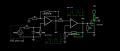
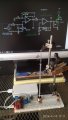
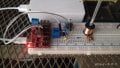
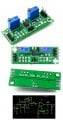
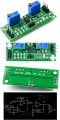
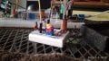
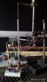
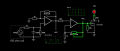
I would like to build a copy of this circuit on a breadboard and have been trying to figure it out through these three images.
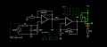
I used Falstad online circuit simulator with a voltage source of 5V and a 100mV test signal.
There's a capacitor connected between the VCC leg of the IC and somewhere else I cant figure out.
I was expecting a more prominent voltage swing when adjusting the potentiometers. There must be something wrong im overlooking as I dont know much about opamps.
Thank you


")