Facebook
 Google
 GitHub
 Linkedin
Hello,
Iam currently designing a mosfet fase dimmer. The dimmer has to dim LED drivers (which are specified for fase dimming) but for ease i have some hallogen light bulbs connected.
The design should have a minimum current of 4A. When iam switching a cold rectified mains signal with a mosfet i get voltage/current dips over the output. I have tried a small snubber but that didn't make a visual change. The whole system is connected to a variac because of the galvanic isolation while testing. If i test outside the variac the automatic fuses turn off all the power. Currently i use a Toshiba K9J90E.
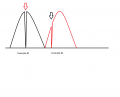
When iam switching like 20 watts nothing happens and it works like it should. When i raise the power to like 50 watts the voltage drop happens and confuses my zero cross detection.
Does someone know how i can resolve these voltage dips?
Do i need to add a way bigger snubber? Do i need to use a inductor coil to smooth out the current with a diode (So the current can flow through the inductor itself while the switch is closed)?
Thank you,
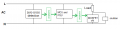
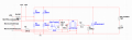
(the schematic is just a visualization of how i made my circuit. Some components could be different from the onces in the schematic.)
(the 4 diodes are in one package, U4 is a mosfet driver, the optocoupler is not a 4n25 and the mosfet is a Toshiba K9J90E)
(the snubber was optional and values gambled)
Iam currently designing a mosfet fase dimmer. The dimmer has to dim LED drivers (which are specified for fase dimming) but for ease i have some hallogen light bulbs connected.
The design should have a minimum current of 4A. When iam switching a cold rectified mains signal with a mosfet i get voltage/current dips over the output. I have tried a small snubber but that didn't make a visual change. The whole system is connected to a variac because of the galvanic isolation while testing. If i test outside the variac the automatic fuses turn off all the power. Currently i use a Toshiba K9J90E.
When iam switching like 20 watts nothing happens and it works like it should. When i raise the power to like 50 watts the voltage drop happens and confuses my zero cross detection.
Does someone know how i can resolve these voltage dips?
Do i need to add a way bigger snubber? Do i need to use a inductor coil to smooth out the current with a diode (So the current can flow through the inductor itself while the switch is closed)?
Thank you,
(the schematic is just a visualization of how i made my circuit. Some components could be different from the onces in the schematic.)
(the 4 diodes are in one package, U4 is a mosfet driver, the optocoupler is not a 4n25 and the mosfet is a Toshiba K9J90E)
(the snubber was optional and values gambled)
Attachments
-
 149 KB Views: 28
Last edited: