 Facebook
 Google
 GitHub
 Linkedin
Hi All,
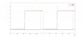
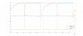
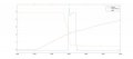
I have built an edge detector that gives a pulse at every falling edge of an incoming signal. A nor gate compares the incoming signal with an inverted and delayed copy (schematic attached). The detection works (figure 1), but I get a very small pulse also at the rising edge. I checked the input of the nor gate (figure 2 and zoom in in figure 3). It seems that the nor gates sees a double low voltage when the capacitor discharges and the other input is rising. Low voltage level for the nor gate is 1.5V max. Do you guys know what's going on?
Thanks
Attachments
-
 20.5 KB Views: 36
 -
 36.3 KB Views: 28
 -
 41.6 KB Views: 24
 -
 35.7 KB Views: 26
")


