Falconry Lure Machine

Thread Starter

Icarus1977

Joined Aug 4, 2014
91
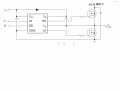
Is it a big job stripping the starter motor down and implementing the necessary changes... Only this is one option I did think possible but do not wish to damage the one I have now as it's brand new and works like a dream.... Not sure if I have the confidence to do it...
 

MaxHeadRoom

Joined Jul 18, 2013
28,698
No effect, unless the negative side were connected to the earth ground somewhere.
You would just treat the -ve side as you would the +ve the positive would become 'Common'.
Max.
 

Thread Starter

Icarus1977

Joined Aug 4, 2014
91
Thought so, bit like electric fencing... If the motor is not running under any serious load would I still need to use a mosfet to switch the load with it all reversed
 

shortbus

Joined Sep 30, 2009
10,045
Thought so, bit like electric fencing... If the motor is not running under any serious load would I still need to use a mosfet to switch the load with it all reversed
Yes, this is how PWM works to control speed. A relay isn't fast enough and the contacts aren't made for PWM.

Changing the brush configuration is not that big of a job. But as max said putting the mosfet/controll between the negative battery post and the motor/winch frame will work too.
 

Thread Starter

Icarus1977

Joined Aug 4, 2014
91
But I would still need to use a mosfet wouldn't I? Would it need to handle high current or would it not matter that much?
 

shortbus

Joined Sep 30, 2009
10,045
But I would still need to use a mosfet wouldn't I? Would it need to handle high current or would it not matter that much?
Yes to the mosfet. It will need to be sized to handle the motor current. This means it will actually be rated for more than the motor current, you always use a device that has a high rating than the load, a safety factor.

Or, if you want to avoid the mosfet (at a greater expense) your 3524 could be used to switch a ssr(solid state relay) of the correct value for the motor. This would also allow you to put the ssr between the positive battery post and the motor.

This is just my thoughts on what your doing, not to say that your doing it wrong, just how I would approach it. The variable speed is what is complicating it. Set a target speed for the lure, 'X' mph or feet per second(fps). Find the circumference of the winch drum, in feet, and then that will give the rpm that it needs to turn. Then figure the gearing ratio from the motor to the drum to make that drum speed happen. This will allow the motor to just be controlled by an on off switch like a starter solenoid. For training the bird to different types of prey, that run at different speeds, changing one pulley on the motor, to change the ratio, would be all that's needed. Nothing real complicated. The K.I.S.S. principle.
 

ronv

Joined Nov 12, 2008
3,770
Yep, The series wound motor will be hard to speed control. When the current is low it wants to spin fast but with lower torque, when the current is high it has high torque but lower speed. So if you take a start up case with say 30% pwm it will start but then really speed up. It will end up spinning at some speed but it won't be 30% of full speed.

http://www.microchip.com/stellent/groups/SiteComm_sg/documents/DeviceDoc/en543041.pdf

But if you want to try it I have some big PFETs. I can mail you a few. 2 or 3 in parallel should be more than enough.

http://www.irf.com/product-info/datasheets/data/irf4905.pdf
 

Thread Starter

Icarus1977

Joined Aug 4, 2014
91
Wish I could, already built the unit and have it working but at times such as loading the spool or for initial training I need to be able to vary the speed of the unit...

It's not going to be used all the time, it's a safety feature that I wish to incorporate as loading the spool initially was dangerous and could have seriously hurt someone, in future I will design it properly but as I have a few friends starting out in falconry with un-entered birds of prey and whilst the cover is too high due to a few mild winters we need something to help train the birds so I quickly built this not thinking how difficult the control side would be...

Never expected it to pull 67A full load...

I have less than a month to train the birds ready for the season starts on the 1st October to 31st March...

I was initially going to use a set of gears from a mountain bike and work it that way, but could not find suitable parts in the local skips...
 

Thread Starter

Icarus1977

Joined Aug 4, 2014
91
Can any mosfet be wired in parallel to take the high current?

Just ordered the IRS4905 so should be here in a days time...

So how do I use them, in the current circuit?

I know that I need to current limit the gate I presume RG = Resistor Gate, but I am getting confused with the data sheet can someone point me in the right direction please...
 

Attachments

Last edited:

Bernard

Joined Aug 7, 2008
5,784
My gut feeling is that we will blow some FETs. On my electric tractor, if the speed was advanced a little to fast it melted some FETs, 3 in parallel, 120 V @ 80 A each. & only 250 W, 22V motors. Even had over current protection, but maybe was too slow.
 

Bernard

Joined Aug 7, 2008
5,784
With circuit on post # 112, I can do no better than 10% to 90 % duty cycle & wide swing in frequency when breadboarded. In an attempt to give 0 to 100% duty, 555 became just a fixed freq. osc. to generate a tringular signal & a comparator to give the PWM. R2 & R3 selected to give desired duty cycle, about 9.1 k. U3, 555, is an inverter/ driver. To provide over current protection, used a 4N25 opto isolator with LED Vf of 1.1V. With a current sensing R of about 10 m ohms, transistor should start conducting at about 100 A, which then brings + input of comparator low & pin 3 of U3 high- shutting off FETs. All suggestions or corrections welcomed.
 

Attachments

Bernard

Joined Aug 7, 2008
5,784
A possible current sense resistor might be made from 10 , 4.6 in lengths of stainless steel wire soldered to two strips of copper. One ohm of 1 mm SS wire took 46 in. Also found .22 ohm, 3 W Rs for 3/ US $1.00, or about $ 7.00 worth.
 

Thread Starter

Icarus1977

Joined Aug 4, 2014
91
Getting interesting this post, so I have now in my hands 4 x IRF4905... I have the IRS2109 outputting a 10Khz PWM Square Wave...

Now then should I use more than one as they are rated at 74A, so would two connected in parallel give me what 148A or does it not quite work like that?

You can probably skip the FET driver and just drive it with the 555 like this:

Use a large heat sink for the FETs and diode.
Hi Ronv, what value resistors are you using for R1 & R4 does the number 51 mean an ohm value or something else?

So I use dump the half bridge driver, and just use a single output from the IRS3524 pin 13 would that give me something to test out...


What is diode D3 being used as Ronv, why use a low drop power schottky rectifier...

Hope you don't mind me re-posting your image?

 
Last edited:

Thread Starter

Icarus1977

Joined Aug 4, 2014
91
With the IRF4905 it has an RDSon value of 0.02ohms, VDSS of 55V and an ID of -74A...

So do I require a resistance of 0.02ohms or have I got something so very confused?

Still trying to get to grips with using a mosfet, the basics are getting me confused...

Is the sense resistor used as part of the motor overcurrent protection?

How can we protect the motor should things go wrong?

Been doing some research, so it's a 51ohm resistor you are using, how was this calculated?
 
Last edited:

shortbus

Joined Sep 30, 2009
10,045
With the IRF4905 it has an RDSon value of 0.02ohms, VDSS of 55V and an ID of -74A...

So do I require a resistance of 0.02ohms or have I got something so very confused?

Still trying to get to grips with using a mosfet, the basics are getting me confused...

Is the sense resistor used as part of the motor overcurrent protection?

How can we protect the motor should things go wrong?

Been doing some research, so it's a 51ohm resistor you are using, how was this calculated?
The RDSon is the resistance in the mosfet when it is on, with ~10V on its gate. This is one of the factors makes the mosfet overheat.

The 51ohm gate resistor is to prevent gate "ringing", this is an oscillation between on/off when the mosfet turns off. It is usually a value between 10 -100ohms. Value not that important, but gate resistor is important to life of mosfets. 51ohm is a good average standard to use.

Personally I'd have a switch and starter relay/solenoid in the circuit. This would act as a 'dead man' control. This is an example of the solenoid, its called a 'ford solenoid' but the same thing is used in many other makes too, ford was just the first. http://www.amazon.com/Ford-SW3-Starter-Solenoid-Relay/dp/B004PKC1YO I went and had a look on a Lucas site, looks like a Lucas 5037 is a ford type solenoid. An auto wrecking yard would have these. This would go in the main positive wire to the motor. A push button type switch, handheld would be the control to start and stop the lure. The speed controller circuit would be separate thing, not controlled by this push button. Doing it this way would allow the lure to be started and stopped at will, not waiting for the speed circuit to start up. Using the solenoid would just control the motor on and off, the speed control would just be working in the backround until needed. A toggle switch would then be used to shut off the speed control at the end of the training time.

The motor itself is going to be the most robust item in the whole equation. Wouldn't worry about its protection too much. It's all about the electronics protection, not the motor.
 
Last edited:

Thread Starter

Icarus1977

Joined Aug 4, 2014
91
Hi Shortbus,

I would love to do it that way, but not sure if I could as I wish to incorporate a remote control into the circuit as the birds are not stupid and soon workout that the button you are holding triggers the dummy bunny which equals food so wait by you till the food arrives therefore refusing to chase the bunny... the idea is that I can be anywhere within reason and the bunny suddenly appears as if by magic from cover... I wish to have the remote connected if possible to the shut down connection on pin 10 of the LM3524 with the entire control circuit being supplied from a separate 12V supply with the motor running from a much bigger 12V power supply...

But I have just connected up the two IRF4905, applied power to them and instantly they were fully switched on not sure if there is an issue with them, no short circuits were located... just unsure why this could be unless I have inadvertently reversed the connections would that cause the same issue?

The control circuit had no effect they were instantly running very hot!!!! Removed control circuit from circuit and found it had no effect the unit was still fully switched on...

Using a 47ohm resistor on the gate...

The pins left to right are Gate, Source and Drain ???

I have the two Source pins and the two Drain pins connected together with +12V applied to the Source Pins and the Drain pins connected to the motor with the motor chasis connected to ground...
 

Attachments

Last edited:
Top